


F16: DC Braking Injection Frequency
Function F16 changes the frequency at which DC Braking begins during
deceleration. The factory setting of 1.5 Hz can be changed to any number
between 1 and 10 Hz, in increments of 0.1 Hz.
F17: DC Braking Level
Function F17 changes the DC braking level from the factory setting of 8.0% to
any number between 0 and 20% in increments of 0.1%.
F18: Electronic Motor Overload Protection
Function F18 changes the current limit from the factory setting of 100% to any
number between 0 and 200% in increments of 1%.
1) Set F18 so that F18 = motor current rating / inverter current rating.
2) While load is < 100% of motor current rating, operation may continue
indefinitely. When load reaches 150% of motor current rating, operation
may continue for only 1 minute more, after which the electronic thermal
protection is activated and inverter output is shut off. The LED display
flashes “OLI”. To resume operation, push the RESET button or activate
the external reset terminal.
3) The electronic thermal protection activation level automatically reduces
to a lower level at low frequencies to compensate for the motor’s lower
heat dissipation efficiency at lower speeds.
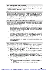
F19: Multi-function Input Terminal 6
F20: Multi-function Input Terminal 7
F19 changes the function of input terminal 6 (factory setting is “Preset Speed
1”) and F20 changes the function of input terminal 7 (factory setting is “Reset”).
Either terminal can be set for any of the following functions: “Jog” (“001”),
“Preset Speed 1” (“002”), “Emergency Stop” (“003”), “External Base Block”
(“004”), “Reset” (“005”), or “Preset Speed 2” (“006”).
Note on Emergency Stop
: When F20 = “003” and terminal 6 is shorted to
terminal 5 (12V), inverter decelerates motor to a stop (ignoring F14 setting)
and LED display flashes “E.S.”. After emergency stop signal is removed,
either turn RUN switch OFF and ON (if F10 = “001”) or push RUN key (if
F10 = “000”) to restart inverter. If stop signal is removed before motor
stops, inverter still executes emergency stop.
Note on External Base Block
: When F20 = “004” and terminal 6 is
shorted to terminal 5 (12V), inverter output immediately shuts off. The LED
display flashes “b.b.” After base block signal deactivated, either turn the
RUN switch OFF and ON (if F10 = “001”) or push the RUN key (if F10 =
“000”) to restart the inverter.
Note on Preset Speed 3 (SP3)
: A single switch closure at either terminal
6 or terminal 7 (depending on settings of F19 and F20) can execute Preset
Speed 1 (SP1) or Preset Speed 2 (SP2). To execute Preset Speed 3
(SP3), switches at both terminals 6 and 7 must be closed with F19 and F20
set for “002” and “006” or “006” and “002”.
Artisan Technology Group - Quality Instrumentation ... Guaranteed | (888) 88-SOURCE | www.artisantg.com