


Description of Programmable Functions
F01: Acceleration Time
Function F01 can be changed to adjust the acceleration time from the default
setting of 5.0 seconds to any time between 0.1 and 999 seconds.
Set Frequency
Acceleration time = F01 x
60 Hz
F02: Deceleration Time
Function F02 can be changed to adjust the deceleration time from the default
setting of 5.0 seconds to any time between 0.1 and 999 seconds.
Set Frequency
Deceleration time = F02 x
60Hz
F03: Start / Stop Control from TM2
Function F03 sets the function of input terminals 3 and 4, provided that function
F10 is set at “001” for external control operation. The default setting of F03 is
“000”, which configures input terminal 3 for a “Forward/Stop” switch (close to
run forward, open to stop) and input terminal 4 for a “Reverse/Stop” switch
(close to run reverse, open to stop). The alternate setting of F03 is “001”, which
configures input terminal 3 for a “Run/Stop” switch (close to run, open to stop)
and input terminal 4 for a “Forward/Reverse” switch (close for forward direction,
open for reverse).
F04: Direction Selection
Although there is no Forward/Reverse push button on the digital control panel, it
is possible to change motor direction without changing the motor connection by
changing function F04. The factory setting is “000” for forward direction.
Changing F04 to “001” will result in reverse direction. NOTE: When F22 =
“001”, reverse is disabled and F04 can not be set to “001”. If it is, the keypad
indication will display the error message “LOC”.
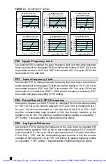
F05: V/F Pattern Setting
Function F05 can be changed from its factory setting of “004” to any number
between “001” and “006”. Settings “001” through “003” are to be used only
when the inverter is configured for 50 Hz input power. Settings “004” through
“006” are to be used only when the inverter is configured for 60 Hz input power.
The three different settings for each input frequency control the ratio of output
voltage to output frequency. The factory setting of “004” with 60 Hz input power
produces a constant volts/frequency ratio between output frequencies of 0 to 60
Hz (above 60 Hz, the output voltage is fixed). The alternate settings either
boost the voltage at lower frequencies for higher starting torque (F05 = “002” or
“005”) or reduce the voltage at lower frequencies for applications where the
torque increases with speed, like a fan (F05 = “003” or “006”). See Fig. 10.
Artisan Technology Group - Quality Instrumentation ... Guaranteed | (888) 88-SOURCE | www.artisantg.com