


Step 5 – Electrical Connections
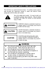
CAUTION
l
The PCB of the inverter is vulnerable to static electrical
charges. Do not contact the PCB.
l
Choose the appropriate power source with correct
voltage settings for the input voltage specification of the
AC inverter.
l
Do not use a separate device to switch ON or OFF
motor during operation. Otherwise, the inverter may
experience an over-current breakdown.
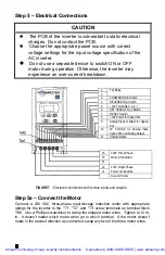
1
Trip Relay
2
3
FORWARD Run Switch
4
REVERSE Run Switch
5
+12V Terminals 3, 4, 6, 7
6
SET SPEED 1 Run Switch
7
RESET Switch
8
+10V Power for Speed Pot
9
Analog Input or Wiper for Speed
Pot
10
0V Common for Analog Input,
Speed Pot, and Analog Output
11
Analog Output
FIGURE 7
–
Electrical connections with remote inputs and outputs.
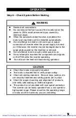
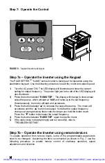
Step 5a – Connect the Motor
Connect a 230 VAC three-phase squirrel-cage induction motor with appropriate
ratings for the inverter to the “T1”, “T2”, and “T3” screw terminals on terminal block
TM1. Use a Phillips screwdriver to clamp the stripped motor wires. Tighten to 12 lb-
in. It doesn’t matter which motor wires go to which terminal. If the motor doesn’t
rotate in the desired direction as connected, swap any two of the three motor wires.
T3
230V Three Phase
T2
Motor Connections
T1
L2
115V Single Phase
L1
Power Connections
Ground Screw
Artisan Technology Group - Quality Instrumentation ... Guaranteed | (888) 88-SOURCE | www.artisantg.com