background image

3

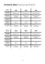
Art.-Nr.

Item No

2003A

2004A

2008A

Einbaumaße

Instl dim

200 x 203 x 92 mm

250 x 253 x 92 mm

250 x 253 x 92 mm

Zuleitungen

Supply line

2 x  hinten

/back


 Ø 25 mm

4 x  hinten

/back


 Ø 25 mm

8 x  seitlich

/lateral


 Ø 25 mm

Nivellierbar

Height adj

Schutzart

Protection

IP54

IP54

IP54

Belastbarkeit

Load

Flächenlast

/Area load


max� 900 kg

Flächenlast

/Area load


max� 900 kg

Flächenlast

/Area load


max� 900 kg

Art.-Nr.

Item No

2003Q

2004Q

2008Q

Einbaumaße

Instl dim

200 x 203 x 92 mm

250 x 253 x 92 mm

250 x 253 x 92 mm

Zuleitungen

Supply line

2 x  hinten

/back


 Ø 25 mm

4 x  hinten

/back


 Ø 25 mm

8 x  seitlich

/lateral


 Ø 25 mm

Nivellierbar

Height adj

Schutzart

Protection

IP54

IP54

IP54

Belastbarkeit

Load

Flächenlast

/Area load


max� 900 kg

Flächenlast

/Area load


max� 900 kg

Flächenlast

/Area load


max� 900 kg

Technische Daten

/Technical specifications

Содержание 20 A/Q Series

Страница 1: ...Bedienungsanleitung Instruction Manual 20er A Q Serie 20 A Q Series ...

Страница 2: ...2 Inhalt Contents Technische Daten 3 Produktbeschreibung 4 Montageanleitung 5 Gebrauchshinweise 13 Technical data 3 Product description 4 Assembly instructions 9 Instructions for use 13 ...

Страница 3: ...a load max 900kg Flächenlast Area load max 900kg Flächenlast Area load max 900kg Art Nr Item No 2003Q 2004Q 2008Q Einbaumaße Instl dim 200x203x92mm 250x253x92mm 250x253x92mm Zuleitungen Supply line 2x hinten back Ø 25mm 4x hinten back Ø 25mm 8x seitlich lateral Ø 25mm Nivellierbar Height adj Schutzart Protection IP54 IP54 IP54 Belastbarkeit Load Flächenlast Area load max 900kg Flächenlast Area loa...

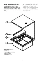
Страница 4: ...es Exemplarisch ist der Bodentank 2003A abgebildet Das Montageprinzip gilt für alle Bodentanks der 20er A Serie 2003A 2004A 2008A und der 20er Q Serie 2003Q 2004Q 2008Q The 2003A floor tank is shown as an example The installation principle applies to all floor tanks from the 20 A Series 2003A 2004A 2008A and the 20 Q Series 2003Q 2004Q 2008Q ...

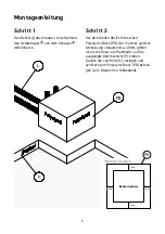
Страница 5: ...ießen des Estrichs einen Polystyrol Block PB der in seiner äußeren Abmessung umlaufend ca 40mm größer ist als die Dose als Platzhalter auf die ausgelegte Dämmschicht P kleben Danach die Leerrohre L verlegen und senkrecht am Polystyrol Block PB befesti gen zum Beispiel mit Klebeband 40mm 40mm 40mm 40mm Bodensteckdose Ansicht von oben PB ...

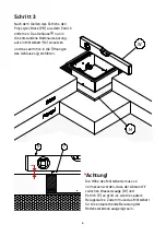
Страница 6: ...ere Belagsstärke Zudem muss das Mörtelbett für die entsprechende Belastung der Bodensteckdose ausgelegt sein 3 E W t Schritt 3 Nach dem Gießen des Estrichs den Polystyrol Block PB aus dem Estrich entfernen Das Gehäuse nun in die entstandene Bodenaussparung auf ein Mörtelbett M einsetzen und die Leerrohre in die Öffnungen des Gehäuses einführen ...

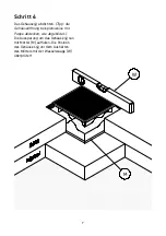
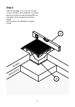
Страница 7: ... abdichten Tipp die Gehäuseöffnung beispielsweise mit Pappe abdecken wie abgebildet Die Aussparung um das Gehäuse nun mit Mörtel M auffüllen Die Position des Gehäuses vor dem Aushärten des Mörtels mit der Wasserwaage W überprüfen ...

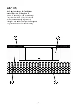
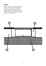
Страница 8: ...en die Steckdosen anschließen den Geräteträger wieder in das Gehäuse einschrauben sowie den Deckel an den Rahmen Danach erst den Belag B im Raum verlegen Der Bodentank ist nun erfolgreich eingebaut Siehe Querschnitt unten E P B M ...

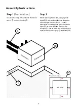
Страница 9: ...the screed a polystyrene block PB with a circumference of approx 40 mm larger than the box in its outer dimension must be glued to the insulation layer P as a placeholder Then lay the conduits L and fix them e g with adhesive tape vertically to the polystyrene block PB P PB L 40mm 40mm Floor socket 40 mm 40 mm View from above PB ...

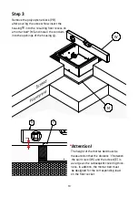
Страница 10: ... a mortar bed M and install the conduits into the openings of the housing Attention The height of the mortar bed must be measured so that the distance t between the spirit level W and the screed E is as large as the subsequent covering thick ness In addition the mortar bed must be designed for the corresponding load on the floor socket ...

Страница 11: ...Seal the housing Tip cover the box ope ning for example with cardboard as shown Now fill the recess around the housing with mortar M Check the position of the hou sing with the spirit level W before curing the mortar ...

Страница 12: ...ter curing connect the sockets screw the device carrier back into the housing and screw the lid onto the frame Lay the remaining covering B in the room The floor socket is now successfully installed See cross section below ...

Страница 13: ... Mängeln technisch elektrisch darf das Produkt nicht in Betrieb genommen werden Das Produkt ist unter Beachtung der nationalen Vorschriften zu entsorgen Irrtümer und technische Änderungen vorbehalten In order to ensure a lasting function of the floor tank the following instructions must be observed Connection repair or maintenance must be carried out by a trained specialist During installation and...

Страница 14: ...ubject to errors and technical changes by BS Bodensteckdosen Systemtechnik GmbH BS Bodensteckdosen Systemtechnik GmbH Dingerdisser Str 36 33699 Bielefeld Germany Tel 49 521 9892780 Fax 49 521 989278 30 info bodensteckdosen com www bodensteckdosen com ...

Отзывы: