BA-117/1EA MZR.5300.01
Please keep a copy of the operating instructions.
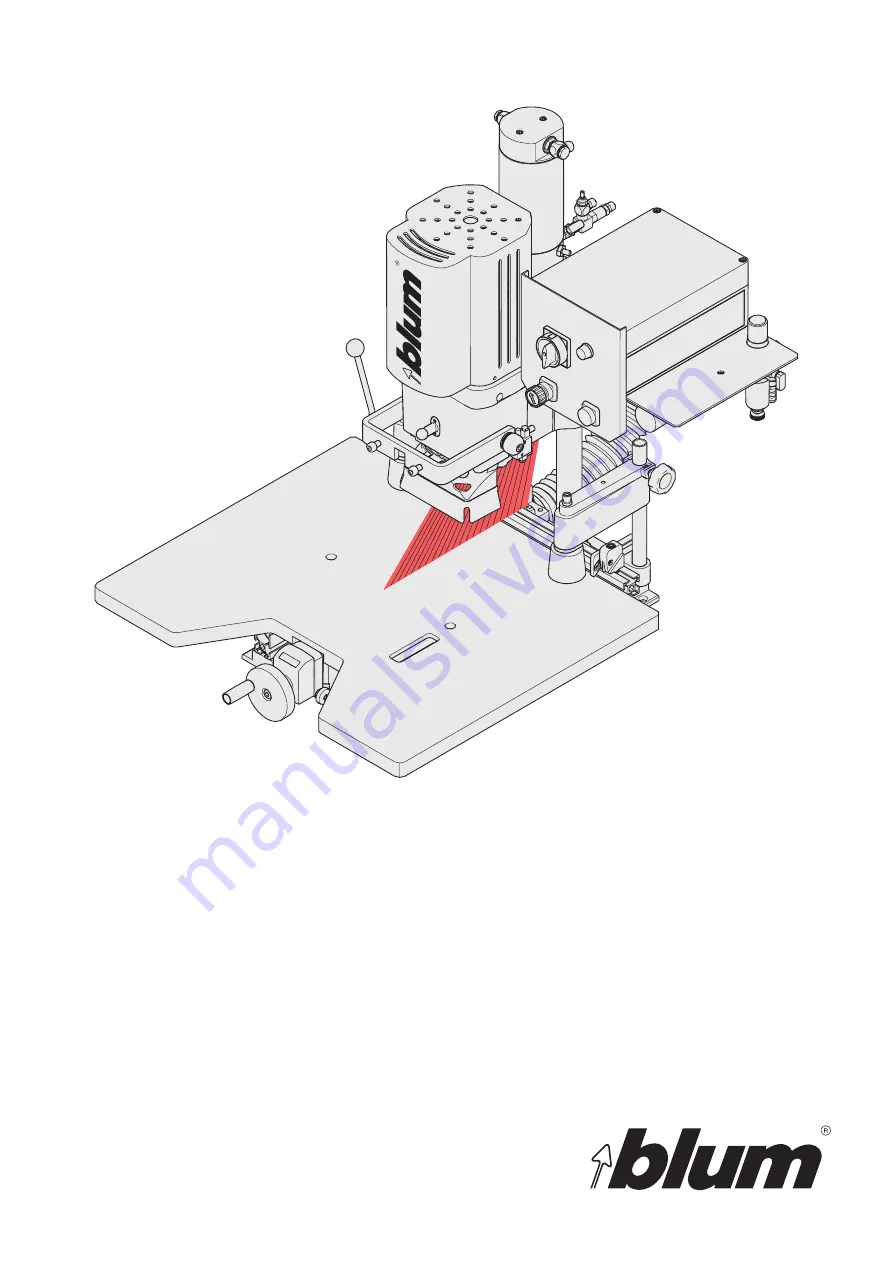
Laser module MZR.5300.01
Work steps should only be carried out by a licensed electrician!
EA
Страница 1: ...BA 117 1EA MZR 5300 01 Please keep a copy of the operating instructions Laser module MZR 5300 01 Work steps should only be carried out by a licensed electrician EA ...
Страница 2: ... contents Contents A Reading guide and safety instructions 3 B Technical Data 5 C Mechanical assembly of laser module 6 D Electrical connection of laser module 8 E Adjusting laser 11 F Troubleshooting 12 G Electrical circuit diagram 13 ...
Страница 3: ... laser module is not intended for children Trained personnel are required to monitor the operation of the laser module in schools training facilities hobby and self help workshops A 3 Danger information The safety and danger information in the MINIPRESS P MINIDRILL P operating instructions must be followed when starting up operating retrofitting servicing repairing and dismantling the MINIPRESS P M...
Страница 4: ...cations The manufacturer does not assume liability for uses not described in these operating instructions or the MINIPRESS P MINIDRILL P operating instructions A 4 Intended use Safety information This exclamation point indicates important safety information that must be followed Comment This exclamation point indicates a comment If this comment is not followed then assembly machine components as w...
Страница 5: ...nce 250 mm Wavelength 650 nm Operating voltage 2 5 6 V DC Operating current 30 mA Operating temperature 10 40 C Storage temperature 40 80 C Laser class 2M Optics acrylic lens Wirelength 1510 mm Material of housing aluminium Cable type LifYY 2y 0 5 mm fan angle 90 or 60 line thickness 0 5 mm 250 mm Potential of housing VDD ...
Страница 6: ...sembly MZR 5300 01 Power supply unit 1 screw DIN 912 M 4x16 ASTM F 912M 2004 Cable clips Label C 2 MINIPRESS P preparation ATTENTION The main switch does not disconnect the machine from the air pressure system Set main switch 3 1 to Pos 0 Disconnect electrical and pneumatic connections from the machine Remove all inserted drill bits ATTENTION gash injury 3 1 ...
Страница 7: ...e C 3 Laser module assembly Insert mounting screw into the mounting hole on the backside of gearbox housing and rotate the screw 2 turns clockwise Place the laser module on to the bolt slide to the right Temporarily tighten the screw using the allen key provided ...
Страница 8: ... assembly machine Remove the screws of the control unit housing using a scre wdriver Turn the screws counter clockwise Never work on components or control unit parts that are still energised Always disconnect electrical power from machine and set the main switch to 0 before starting work Follow all LOCKOUT TAGOUT procedures establishment by management Always use a voltage tester to ensure that com...
Страница 9: ... module Snap the transformer into place on the DIN rail Mount the cable bushing Set aside enough remaining cable up to the cable tie Thread the cable as shown Attach cable along the pneumatic lines using the cable ties Feed the cable through the cable bushing ...
Страница 10: ...e cover on the control unit housing Turn the screws clockwise using a screwdriver Never work on components or control unit parts that are still energised Always pull the mains plug and set the main switch to 0 before starting work Always use a voltage tester to ensure that components as well as control unit components are not energised before starting work Put the label on the machine Carry out th...
Страница 11: ... assembly machine Keep your hands out of work area A Main switch 3 1 to pos 1 Laser line must be visible E 1 Adjusting laser to zero position Slightly loosen sub assembly screw using a wrench counter clockwise Set laser line to the zero position Tighten screws using wrench clockwise E 2 Check the laser angle If laser angle is correct all work steps are done The machine with the laser module is rea...
Страница 12: ...crew using allen key clockwise Only carry out the following steps when the laser angle is not correct Only carry out the following steps when the laser is not perpendicular The laser beam is not perpendicular when it has moved from the zero position due to the stroke movement Loosen set screw using allen key counter clockwise Move laser diode until the laser beam is perpendicular Re tighten set sc...
Страница 13: ...0 F1 250V dm5x20mm 1 6AT 1788700 1S2 250V 6A G1 4 3988890 H1 230VAC 2456160 K1 400V max 690V 12A 2456300 M1 1 1kW 220V 60Hz 3244009 C 25µF 400VDB 2649801 1 2 4 1S2 P 0V 220V 0V 3 6V T1 N L POTENTIOMETER brown blue F1 T1 6A PE N L1 white black PE green V2 U1 W2 W1 V1 U2 H1 X1 X2 1 M1 1x220V 60Hz S6 60 ED 7 3A 1 1kW 3325 min C 25µF 400VDB C 1 3 5 2 4 6 S1 7 8 ...