Do Not Duplicate, Alter, or Copy without the Express Written Consent
of BlueSky Mast, Inc. Copyright 2016 Allendale LLC All Rights Reserved
AL350G Lift Series
Quick Reference Sheet
-
Primary Guying
DEPLOYMENT
Read Manual Before Use
Refer to detailed instructions in the
AL350G Lift Series Manual at all times
01
/1
7
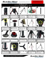
Stand the tripod up and release
the large Velcro Strap at the
bottom.
Open the tripod legs and lock
the cross bars. Push them all
the way down to fully engaged.
Stake
ONLY
the
LEFT HOLES
on the base plates of the 2
extended tripod legs.
Extend and tighten the 2 tripod
legs adjacent to the winch.
DO NOT
extend the tilt leg.
1
2
3
4
Locate the mounting pole. It’s
the only pole without a gold
insert.
Insert the mounting pole until 1
hole is showing below the cam
lock and lock the cam lock.
Level the tripod by adjusting the
tripod legs. Make sure all 3
bubble levels read level.
Add Red Primary Guy Ring.
DO NOT
secure it at this time.
Mount your equipment to the
mounting pole, connect and
secure all cables.
Extend the tilt leg and tighten
the turn knob. Make sure all 3
tripod struts are facing inward.
5
6
7
8
10
9
12
13
14
15
11
Attach the winch handle. Pay
out the cable by turning the
winch handle counter clockwise
The cable should hang freely on
the left side of the winch and
should not hang over anything.
Stake the remaining holes on all 3
tripod legs.
Locate the
LIFT BASE PLATE
.
Insert the lift base plate into the
bottom of the mounting pole.
Center the strut base plate
under the tripod and align with
the 3 tripod legs..
Release the Velcro straps
holding the tripod struts on each
of the 3 tripod legs.
Pass the cable through the 2
rollers on the lift base plate and
back up to the ball stop holder.
Pull the pin to secure the ball
stop. Confirm the cable is taut
and the lift base plate is secure.
Locate the
STRUT BASE
PLATE.
16
19
17
18
20


