Page 1 of 2
BR-EVAL-LE4.0-X2A Quick Start Guide v3.1.0
Copyright © 2002-2012 BlueRadios, Inc.
7173 S. Havana Street, Suite 600
•
Englewood, CO 80112 •
(
303)-957-1003
www.BlueRadios.com
n
Blue
™
BR-EVAL-LE4.0-X2A Quick Start Guide
1 Kit Contents
n
Blue
™
USB Dongle (Dongle) w/
n
Blue
™
BR-LE4.0-X2A Module (X = S for Single Mode, D for Dual Mode)
n
Blue
™
Development Board (DevBoard) w/
n
Blue
™
BR-LE-4.0-X2A Module and Micro-USB cable.
2 Important Notes
The modules operate at a supply voltage (VDD) of 2.0-3.6V, 3.0V is recommended.
The maximum voltage level on any pin should not exceed 3.6V.
The I/O is NOT 5V tolerant.
<cr>
= Carriage Return (ENTER key, 0x0D),
<cr_lf>
= Carriage Linefeed (0x0D0A)
3 Drivers
The Dongle and the DevBoard both require virtual COM port drivers, which can be obtained from:
http://www.ftdichip.com/Drivers/VCP.htm
. Windows will automatically locate and install these drivers.
4 Documentation and Firmware Updates
Module documentation and firmware updates can be downloaded from:
http://www.blueradios.com/forum
.
5 Quick Start Using Windows and HyperTerminal
5.1 Terminal Setup
1.
Plug the Dongle into an available USB port on your PC and a red power
led will come on. Follow the prompts to install the device and be sure to
note the COM port that has been assigned to the Dongle. The assigned
COM port number can be found in Device Manager under Ports.
2.
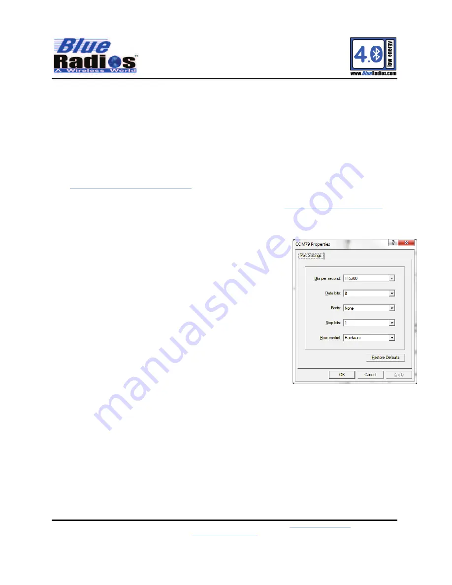
Open a new HyperTerminal session named “Master-Dongle”, with factory
default settings (do not echo characters or append any additional line
feeds). Connect to the COM port assigned to your Dongle at 115200, 8-
N-1, with hardware flow control.
3.
On the DevBoard set the power switch to the USB position and then
connect the provided USB cable to the USB connector labeled “UART”.
Plug the cable into an available USB port on your PC and the red VBUS
led will come on. The PIO5 led will also start pulsing every 2 seconds,
indicating the module is discoverable. The DevBoard will install two COM
ports, the port with the higher number is the one you will be using.
4.
Open another new HyperTerminal session named “Slave-DevBoard" with
factory default settings (do not echo characters or append line feeds).
Connect to the COM port assigned to your DevBoard at 115200, 8-N-1,
with hardware flow control.
5.
To verify communication with each module, type “AT<cr>” in each terminal and the module will respond OK.
COMMAND:
AT
<cr>
RESPONSE:
<cr_lf>
OK
<cr_lf>
6.
Read and record the
Bluetooth
Address from the DevBoard by typing “ATA?<cr>” in the DevBoard terminal.
COMMAND:
ATA?
<cr>
RESPONSE:
<cr_lf>
OK
<cr_lf><cr_lf>
ECFE7EXXXXXX
<cr_lf>
5.2
Making a Low Energy (LE) Connection
1.
If you are using a Dual Mode module, make the DevBoard discoverable by typing “ATDSLE<cr>” in the
DevBoard terminal. (Single Mode modules are LE discoverable by default.)
COMMAND:
ATDSLE
<cr>
RESPONSE:
<cr_lf>
OK
<cr_lf>
2.
Next, try to discover the DevBoard from the Dongle by typing “ATDILE<cr>” in the Master-Dongle terminal.
COMMAND:
ATDILE
<cr>
RESPONSE:
<cr_lf>
OK
<cr_lf>
The Dongle will respond with multiple discovery events depending on how many LE devices are in the area.
By default the module does an active scan discovery, so up to 2 events may print for each discovered device.


