-25-
Revision 5/F3534
©
Moffat Ltd, April 2005
Turbofan Convection Oven
Thermostat faulty
Set thermostat to 200°C or 400°F. Check the
voltage out of terminal two on the thermostat. If
there is no voltage then the thermostat is faulty—
replace.
If the voltage is correct and the heating light is on
then check all wiring to elements.
6.1.10 NO TEMPERATURE CONTROL
Thermostat faulty
With thermostat in off (vertical) position, the
heating indicator should be off. If not then the
thermostat is faulty—replace.
Check that the thermostat phial is in correct
location and check for broken capillary tube—
replace if damaged.
Place an accurate digital thermometer probe in
centre of oven. Set thermostat to 180°C or
355°F. Close the oven door and allow oven
thermostat to regain temperature. If temperature
overshoots by 50°C and continues, switch off and
replace.
6.1.11 SLOW RECOVERY
Thermostat out of calibration
Place an accurate digital thermometer probe in
centre of oven. Set thermostat to 180°C or 355°
F. Close the oven door and allow oven
thermostat to cycle on and off twice. Record
oven centre temperature for the next thermostat
on and off cycle. The thermostat should cycle on
and off between 165°C and 195°C or 330°F and
385°F when set to the above temperature. If
oven temperature is outside these ranges, then
the thermostat requires recalibration.
NOTE:
Thermostat cycling span should be ±15°
C or 27°F
6.1.12 BOTTOM ELEMENT NOT WORKING
Element faulty (blown)
With the thermostat on and heating check voltage
across bottom element terminals at rear of oven.
If the voltage is correct then check the current
draw of element. If there is no current draw then
element is faulty—replace.
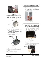
Figure 6.1.6
Bottom Element
Terminals
Hold mini-contactor faulty - to S/N 232053
Check voltage to terminal 1 on oven thermostat.
If there is no voltage then check voltage through
terminal 21 and 22 on mini contactor (inside
control panel). If there is no voltage to terminal
21 then check wiring. If there is no voltage to
terminal 22 then check that the contact indicator
on centre of the contactor is in ‘0’ position. If
indicator is in ‘0’ position and there is no voltage
to 21 then replace contactor.
If indicator is in the ‘1’ position then check the
voltage across contactor coil terminals A1 and
A2.
NOTE:
There should be no voltage across these
terminals when ‘Roast ‘n Hold’ is not
selected.
If the indicator is in position ‘1’ with no voltage
across A1 and A2 then the contactor is faulty—
replace.
Contact
Indicator
Terminal A1
Terminal 21
Terminal 22
Terminal A2
Figure 6.1.5
A
7
4
1
B
Figure 6.1.4
then the relay is faulty - replace.
NOTE:
The relay should only be energised when
the ’Roast ’n Hold’ switch is depressed.
If there is voltage at terminal 1 then check all
wiring to the thermostat.


