background image

®

Contact 1-800-762-1142 for assistance.

Do not return to place of purchase.

9

Owner’s manual: model 233010 outdoor patio heater          6/8/04

®

Contact 1-800-762-1142 for assistance.

Do not return to place of purchase.

10

Owner’s manual: model 233010 outdoor patio heater          6/8/04

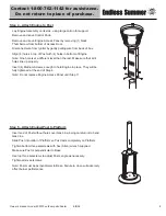
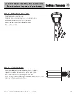
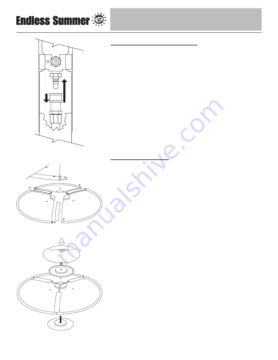
Step 6 – Connect Gas Line to Engine

Attach Gas Line to Control Valve:

Pull collar of Gas Line back.

Insert Gas Line over Control Valve. 

Release collar and it should lock in place. (Tip – push Gas Line up from 
bottom of Post to make a good seating before releasing the collar.)

Gently tug on line to test for proper connection. If Gas Line moves you 
are not properly connected. Do not proceed until you have a proper 
connection.

Fully tighten the (4) screws from Step 4.

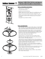
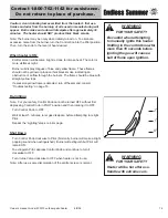
Step 7 – Assemble dome

Note: 

Each dome section has a pin mounted in place in the rolled bottom 

edge. If necessary for proper alignment of dome sections, loosen each 
screw prior to further assembly and retighten after sections are aligned.

With the large side facing up, slide a dome rib on to the same side of 
one dome section as the pin. Slide two dome sections together, allowing 
the exposed end of the pin slide into the rolled edge of the next dome 
section. Line up hole in dome with threaded hole in pin.

Insert one Dome Screw and secure loosely.

Repeat procedure to complete the assembly of all three sections.

Slide Dome bolt through bottom check plate (with small center hump), 
being sure that the rolled edge faces down.

Slide bolt from previous step through the center of the assembled dome 
sections, and be sure that the rolled edge of the check plate fits inside of 
the ends of the three Dome Ribs. Also be sure that the slots in the check 
plate line up with the holes on the dome sections.

Slide the other check plate over the Center bolt with the rolled edge 
facing up, again making sure that the plate fits inside of the Ribs and the 
holes line up with those in the dome.

Spin the medium nut all the way down the bolt, clamping all of the pieces 
in place, making sure that all of the humps fit inside one another.

Fully tighten all of the screws in the rolled edge.

Slide Dome Cap over Dome Bolt, lining up notches in cap with Dome 
Ribs. Thread on finial until tight.

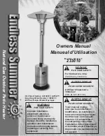
Содержание Endless Summer 233010

Страница 1: ...rnant l installation le fonctionnement et l entretien avant d installer ou de proceder a la maintenance de cet appareil WARNING FOR YOUR SAFETY For Outdoor Use Only Outside any enclosure WARNING FOR Y...

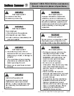
Страница 2: ...this equipment WARNING California Proposition 65 Chemicals known to the state of California to cause cancer birth defects or other reproductive harm are created by the combustion of propane WARNING FO...

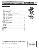
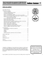
Страница 3: ...tep 9 Secure Gas Line 10 Step 10 Check for Leaks 11 Step 11 Replace Engine Access Panel 12 Step 12 Install Igniter Battery 12 Operation Before Turning Gas Supply ON 13 Before Lighting 13 Lighting 13 R...

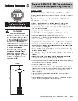
Страница 4: ...children and pets should be carefully supervised when they are in the area of heater Do not hang clothing or other flammable materials either on or near heater Any guard or other protective device re...

Страница 5: ...damage heater or make it unsafe Keep burner area clean of all spiders webs or insects Inspect heater before each use Have heater inspected annually by a qualified service person Check heater immediate...

Страница 6: ...her 56 01 206 1 Large Nut 7 3 8 16 Stainless Steel Hex Nut 56 01 208 12 Small Nut 1 2 1 4 20 Nickel Plated Hex Nut 56 01 209 3 Cap Nut 8 5 16 18 Stainless Steel Cap Nut 56 01 210 1 Finial 7 56 01 103...

Страница 7: ...ct 1 800 762 1142 for assistance Note All hardware is mounted on a cardboard pack and numbered to match their assembly step Additional Requirements The following items are not included but are necessa...

Страница 8: ...Small Lock Washers and 2 Small Nuts per Leg Tighten fully Fully tighten all nuts and bolts from Step 1 Step 3 Insert Gas Line Through Platform Attach Cylinder Cover Insert Gas Line up through large h...

Страница 9: ...rent level than the rest Make sure that all 4 holes line up properly Insert 4 Medium Screws enough to hold Engine in place They will be fully tightened at the end of Step 6 Note Do not replace Engine...

Страница 10: ...de two dome sections together allowing the exposed end of the pin slide into the rolled edge of the next dome section Line up hole in dome with threaded hole in pin Insert one Dome Screw and secure lo...

Страница 11: ...ts Leave Heater on its side for next step Step 9 Secure Gas Line Make sure angled side of Gas Clip pokes up through large hole in Platform Tighten screw until Gas Line is held securely in place Stand...

Страница 12: ...ol valve and re attach making sure connection is secure see Step 6 Retighten Clip If you continue to see bubbles after several attempts contact 1 800 762 1142 for assistance Check Gas Line Fuel Supply...

Страница 13: ...Negative end of battery goes in first Replace battery cover cap by turning cap clockwise Note Once you have successfully completed assembly steps 1 12 you are ready to begin operating your heater Step...

Страница 14: ...er Lighting Note This heater is equipped with a Pilot Light that allows for safer startups and shutdowns Pilot must be lit before Main Burner can be started Push Control Knob IN and turn to OFF Wait 5...

Страница 15: ...ble at night Burner will display tongues of blue and yellow flame These flames should not be yellow or produce thick black smoke indicating an obstruction of airflow through the burners The flame shou...

Страница 16: ...om gasoline or other flammable liquids or vapors q Heater is away from windows air intake openings sprinklers and other water sources q Heater is at least 36 clearance top and 24 clearance side combus...

Страница 17: ...ocouple is not operating correctly Clean dirt from around pilot Tighten connection and perform leak check Replace thermocouple Burner won t light Gas pressure is low Blockage in orifice Control knob i...

Страница 18: ...treme yellow tipping of flame Heater does NOT reach the desired temperature Heater glow is excessively uneven Heater makes popping noises Spiders and insects can nest in burner or orifices This danger...

Страница 19: ...ent weather such as rain sleet hail snow dust and debris If desired cover heater to protect exterior surfaces and to help prevent build up in air passages Never leave LP cannister exposed to direct su...

Страница 20: ...third party failure to perform normal and routine maintenance on the heater shipping damage normal adjustment to burner damage or repairs related to insects birds or animals of any kind and damage du...

Страница 21: ...rnational Requirement 5 90 Canadian National Standard CAN1 2 23 M82 Rating Maximum 40 000 BTU hr input Heat Range Up to 20 foot diameter Fuel Natural Gas Inlet gas supply pressure Maximum 10 5 W C Min...

Страница 22: ...des blessures ou des d g ts mat riels Lire compl tement les instructions d installation d utilisation et d entretien avant de monter l appareil ou de proc der son entretien AVERTISSEMENT Proposition 6...

Страница 23: ...xer le d me l metteur 10 tape 11 Raccorder la conduite de gaz 10 tape 12 Rechercher une fuite potentielle 10 tape 13 Installer le panneau d acc s de la bonbonne 11 tape 14 Replacer le panneau d acc s...

Страница 24: ...p ratures afin d viter qu ils ne se br lent ou que leurs v tements ne prennent feu Ne laissez jamais les enfants et les animaux domestiques sans surveillance lorsque ces derniers sont proximit de l ap...

Страница 25: ...s conditions dangereuses et de nuire au bon fonctionnement de l appareil Veillez ce que la zone du br leur demeure propre et sans toiles d araign es ou insectes V rifiez l appareil avant chaque utilis...

Страница 26: ...er inoxydable M6 56 01 206 1 Grand crou 7 crou hex en acier inoxydable de 3 8 16 56 01 208 12 Petit crou 1 2 crou nickel hex de 1 4 20 56 01 209 3 crou borgne 8 crou borgne en acier inoxydable de 5 16...

Страница 27: ...rot es afin de les faire correspondre aux diverses tapes du montage Accessoires Suppl mentaires Les articles suivants ne sont pas inclus mais n cessaires pour obtenir un assemblage ad quat de votre ra...

Страница 28: ...errez bloc Serrez compl tement tous les crous et toutes les vis de l tape 1 CONSEIL Pour serrer utilisez une cl de 11 mm pour le boulon et une cl de 11 mm pour l crou Step 3 Introduire la conduite de...

Страница 29: ...s six vis de r glage Remarque le p le doit tre perpendiculaire au socle Le non respect de cette consigne risquera de nuire au rendement du br leur tape 4 Fixer le moteur au p le Placez le moteur afin...

Страница 30: ...t en laissant le c t avec cheville glisser dans la partie suivante du d me Alignez le trou du d me avec le trou filet de la cheville Introduisez une vis destin e au d me et introduisez la sans serrer...

Страница 31: ...orgnes Laissez l appareil reposer sur le c t pour l tape suivante tape 9 Fixer la conduite de gaz Assurez vous que l angle de la bride de la conduite de gaz ressorte par le trou de la tablette Serrez...

Страница 32: ...e gaz et de la valve de contr le V rifiez si des bulles apparaissent au niveau des raccords Si les raccords NE pr sentent PAS de bulles le raccord est tanche Si des bulles apparaissent vous venez de d...

Страница 33: ...bas jusqu ce que les trous s alignent sur la partie inf rieure Fixez le panneau d acc s en place avec la vis oreilles qui a t retir e auparavant Replacez le bouton de commande tape 12 Monter la batte...

Страница 34: ...as d usure excessive Testez les parties douteuses afin de vous assurer qu elles ne pr sentent pas de fuite Si le tuyau fuit remplacez le avant d utiliser l appareil Utilisez uniquement un tuyau de rec...

Страница 35: ...use PILOT Ensuite r glez le bouton sur le niveau de chaleur d sir Lorsque l appareil est allum ON La grille de l metteur deviendra rouge vif en raison de l intensit de la chaleur La couleur est plus v...

Страница 36: ...de et autres sources de vapeurs inflammables q L appareil est loin de fen tres bouches d air arroseurs automatiques et autres sources d eau q L appareil se trouve au minimum 91 cm au dessus et de 61 c...

Страница 37: ...leuse Serrez le raccord et d terminez si ce dernier pr sente une fuite Remplacez le thermocouple Le br leur ne s allume pas La pression de gaz est trop basse L orifice est bouch Le bouton de commande...

Страница 38: ...ouvertures permettant la circulation de l air demeurent propres Les indices permettant de d terminer qu il existe un obstacle sont les suivants Il existe une odeur de gaz et la cr te de la flamme est...

Страница 39: ...l abri des intemp ries la pluie la pluie vergla ante la gr le la neige la poussi re et autres d bris Si vous le souhaitez recouvrez l appareil afin de prot ger les surfaces ext rieures Ne laissez jama...

Страница 40: ...sectes oiseaux ou animaux quels qu ils soient ni les dommages li s aux conditions m t orologiques comme il a t tabli dans ce manuel De plus cette garantie limit e ne couvre pas le fini savoir les rayu...

Страница 41: ...dian National Standard Puissance D bit calorifique maximum 40 000 BTU heure CE en entr e de 7 0 po 177 mm P rim tre chauff Jusqu 6 m tres de diam tre Carburant Gaz naturel Pression du gaz d alimentati...

Страница 42: ...42 www bluerhino com 2004 Blue Rhino Global Sourcing LLC All Rights Reserved Made in China Fabriqu pour Blue Rhino Global Sourcing 104 Cambride Drive Plaza Winston Salem NC 27104 tats Unis 1 800 762 1...

Отзывы: