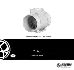
BLAUBERG Ventilatoren Turbo 100 Скачать руководство пользователя страница 1

USER’S MANUAL

Turbo

INLINE MIXED-FLOW FANS

EN

Содержание Turbo 100

Страница 1: ...USER S MANUAL Turbo INLINE MIXED FLOW FANS EN ...

Страница 2: ...ent intended for technical maintenance and operating staff The manual contains information about purpose technical details operating principle design and installation of the Turbo unit and all its modifications Technical and maintenance staff must have theoretical and practical training in the field of ventilation systems and should be able to work in accordance with workplace safety rules as well...

Страница 3: ... work permit for electrical units up to 1000V are allowed for installation and maintenance The present user s manual should be carefully read before beginning works Check the unit for any visible damage of the impeller the casing and the grille before starting installation The casing internals must be free of any foreign objects that can damage the impeller blades While mounting the unit avoid com...

Страница 4: ...icient air flow Do not sit on the unit and do not put objects on it The information in this user s manual was correct at the time of the document s preparation The Company reserves the right to modify the technical characteristics design or configuration of its products at any time in order to incorporate the latest technological developments WARNING Similar to the use of any other household elect...

Страница 5: ...ning use of the appliance by a person responsible for their safety Children should be supervised to ensure that they do not play with the appliance The connection to the supply mains must be made through a means of disconnection which is incorporated in the fixed wiring in accordance with the wiring rules and has a contact separation in all poles that allows for full disconnection under overvoltag...

Страница 6: ...ord set available from the manufacturer or its service agent CAUTION In order to avoid a safety hazard due to inadvertent resetting of the thermal cut out this appliance must not be supplied through an external switching device such as a timer or connected to a circuit that is regularly switched on and off by the utility Ensure that the appliance is switched off from the supply mains before removi...

Страница 7: ...ract ventilation of premises The fan is designed for connection to ø 100 125 150 160 200 250 and 315 mm air ducts The unit is equipped with a two speed motor Ø D B H L Turbo 100 97 195 8 241 255 302 5 Turbo 125 123 195 6 241 255 258 5 Turbo 150 148 220 1 251 265 289 Turbo 160 158 220 1 251 265 289 Turbo 200 199 239 261 278 295 5 Turbo 250 247 287 323 340 383 Turbo 315 310 362 408 424 445 Turbo ХХХ...

Страница 8: ...e arrow on the fan casing must match the air direction in the system Ingress protection rating against access to hazardous parts and water ingress is IPX4 The unit is rated as a Class II electrical appliance The fan is rated for operation at the ambient air temperature from 1 C up to 40 C Power supply V Hz Transported air temperature C 220 240 50 25 60 220 60 25 40 ...

Страница 9: ...ontroller with an electronic thermostat and an integrated temperature sensor Timer based operation logic U1n speed controller with an electronic thermostat and an outdoor temperature sensor fixed on a 4 m cord Timer based operation logic U2 speed controller with an electronic thermostat and an integrated temperature sensor Temperature based switching on off U2n speed controller with an electronic ...

Страница 10: ... a hood in case of vertical fan mounting The outlet spigot must always be connected to the air duct The fan mounting sequence is shown in Fig 3 11 and 14 19 The fan wiring diagrams are shown in Fig 12 13 Some fan models are equipped with a plastic limit stop in front of the L1 terminal Remove the limit stop for connection to the L1 terminal Designation L1 minimum speed terminal L2 maximum speed te...

Страница 11: ...rbo XXX T fan starts running after the external switch supplies control signal to the LT input terminal for example during turning the light on After removal of the control signal the fan continues to run within the set time adjustable with the turn off delay timer from 2 to 30 minutes To adjust the fan turn off delay time rotate the control knob T clockwise to increase and counter clockwise to de...

Страница 12: ...d control knob in the same way The fan functioning logic may be based on temperature or timer controls Turbo XXX Gl1 G1 the fan switches to the maximum speed as the room air temperature exceeds the set point As the air temperature drops down 2 C below the temperature set point or if the initial temperature is below the set point the fan operates with the set speed Turbo XXX GTl1 GT1 the fan switch...

Страница 13: ...mooth speed air flow control from minimum to maximum value Fig 22 TROUBLESHOOTING Problem Possible reasons Troubleshooting When the unit is connected to power mains the fan does not rotate and does not respond to any controls No power supply Make sure the power supply line is connected correctly otherwise troubleshoot the connection error Internal connection fault Contact the Seller Low air flow T...

Страница 14: ...r handling and storage operations to prevent possible damage to the unit Follow the handling requirements applicable for the particular type of cargo The unit can be carried in the original packaging by any mode of transport provided proper protection against precipitation and mechanical damage The unit must be transported only in the working position Avoid sharp blows scratches or rough handling ...

Страница 15: ...eliminated by the manufacturer by means of warranty repair at the factory free of charge The warranty repair includes work specific to elimination of faults in the unit operation to ensure its intended use by the user within the guaranteed period of operation The faults are eliminated by means of replacement or repair of the unit components or a specific part of such unit component The warranty re...

Страница 16: ...e unit by the user Unit repair by any persons without the manufacturer s authorization Expiration of the unit warranty period Violation of the unit transportation regulations by the user Violation of the unit storage regulations by the user Wrongful actions against the unit committed by third parties Unit breakdown due to circumstances of insuperable force fire flood earthquake war hostilities of ...

Страница 17: ...17 EN min 1 m 1 2 ...

Страница 18: ...18 EN QF 3 4 5 6 ...

Страница 19: ...19 EN 7 8 9 10 11 ...

Страница 20: ...20 EN MAX MIN MAX MIN N L2 N L QF QF N L1 L2 S N L M N L1 N L QF M M L2 L1 N L M MAX 12 Turbo XXX ...

Страница 21: ... MAX MIN L2 L1 N L X N L ST QF N L LT L1 X S N L ST QF N L LT L1 X L2 N L ST QF N L LT X N L ST QF N L LT L1 X S N L ST QF N L LT L1 X N L ST QF N L LT L2 X 13 TERMINAL BLOCK FOR 5 CONTACTS TERMINAL BLOCK FOR 4 CONTACTS Turbo XXX T ...

Страница 22: ...22 EN 25 QF 14 15 16 17 18 19 ...

Страница 23: ...23 EN 3030 min 2 min MIN MAX STOP 20 21 ...

Страница 24: ...24 EN 33 min max 22 23 Thermostat control knob Speed control knob Speed control knob Turbo Gl1 GTl1 GSl1 Turbo FR1 Turbo G1 GT1 GS1 ...

Страница 25: ...25 EN 24 25 26 27 ...

Страница 26: ...26 EN 18 28 29 30 ...

Страница 27: ...27 EN Quality Inspector s Stamp Manufacture Date Sold by name and stamp of the seller Purchase Date ...

Страница 28: ...B77EN 05 www blaubergventilatoren de Turbo________________________ ...

Отзывы: