21
CHAPTER 4: Installation
4A.
4-Line units:
4-Line Caller ID units each have two RJ-14C two-line phone-input
connectors; they’re designed to be directly connected to two-line phone jacks.
If your site has standard single-line jacks, and you need to attach three or four
lines to any given 4-Line unit, you’ll need to consolidate the extra lines by
running the included two-to-one condenser cables from the other output of
the cross-connects to the Caller ID’s phone-input connectors. (If you ever
need a replacement for one of these cables, please call Black Box for
technical support.)
If your site
does
have two-line phone jacks, you can run standard phone
cables instead.
4B.
8-Line units:
8-Line Caller ID units each have eight RJ-11C single-line phone-
input connectors; they’re designed to be directly connected to standard
single-line phone jacks. If your site has single-line jacks, run standard phone
cables from the other output of the cross-connects to the Caller ID’s phone-
input connectors. Only one of these cables is included, for initial testing
purposes; additional cables are available as product code EL04MS-MM.
If your site has two-line phone jacks, you’ll need to use line splitters (not
included) to put the lines on separate connectors.
5. Run an RS-232 cable (not included) from the DB9 female RS-232 OUT port
of your single Caller ID unit or the first (highest-numbered) unit in your
daisychain to an RS-232 serial port on the DTE that will be receiving the
Caller ID information. If the DTE is a PC running terminal emulation, and
you’re connecting the Caller ID unit to one of its DB9 male serial ports, you’ll
need a straight-through-pinned (Pin 1 to 1, 2 to 2, etc) DB9 male-to-female
cable (not included) such as product code EDN12H-MF. If you’re connecting
the Caller ID unit to an actual terminal, or to one of a PC’s DB25 serial ports,
you’ll need a DB9 male to DB25 female cable pinned as shown in Table 4-1
on the next page. If for whatever reason you want to connect the Caller ID
unit to a DCE, please call Black Box for technical support.
CAUTION!
To prevent noise problems, the Caller ID unit is grounded through this
serial cable and the DTE, not through its own power supply; the DTE
must, in turn, be grounded to your site’s grounding system through its
power cord or power supply. The grounding obtained through a
standard 3-prong AC-power outlet and power cord should be sufficient,
providing the AC outlet has been properly installed. Failure to properly
ground the DTE might cause the DTE and/or the Caller ID unit to
malfunction or be damaged, and also creates an electrical and fire
hazard. Do
not
use AC isolation plugs.
Содержание TE120A
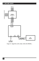
Страница 13: ...12 4 AND 8 LINE CALLER ID Figure 2 3 Signal flow with a 4 Line Caller ID TE120A ...
Страница 14: ...13 CHAPTER 2 Introduction Figure 2 4 Signal flow with an 8 Line Caller ID TE121A ...
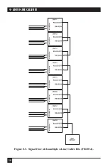
Страница 15: ...14 4 AND 8 LINE CALLER ID Figure 2 5 Signal flow with multiple 4 Line Caller IDs TE120A ...
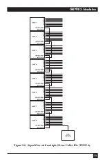
Страница 16: ...15 CHAPTER 2 Introduction Figure 2 6 Signal flow with multiple 8 Line Caller IDs TE121A ...
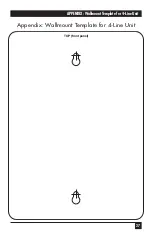
Страница 28: ...27 APPENDIX Wallmount Template for 4 Line Unit Appendix Wallmount Template for 4 Line Unit TOP front panel ...
Страница 29: ...NOTES ...

