24
SERVLINK™
4. Find the power patch cord that came with your Management Module. It will
have an IEC 320 female connector on one end and an IEC 320 male
connector on the other. Plug the male end of this cord into the power port
marked “OUT” on the Module. Plug the other end of this cord into the
power inlet on the ServLINK unit.
5. Finally, run the ServLINK’s own power cord from its own inlet to a properly
rated wall outlet. The ServLINK, the Module, and the wall outlet should now
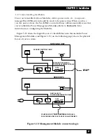
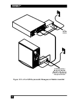
be interconnected, power-wise, as shown in Figure 3-10.
Figure 3-10. Attaching the power cords.
6.
Optional:
To ensure that you have constant dial-in reboot access to your
ServLINK unit, you can connect a separate modem and phone line to the
Management Module, so that you have a secondary way to reboot the
ServLINK in case the primary phone line is tied up or goes down.
To do this, attach the RJ-45F-to-DB9M adapter included with the
Management Module to the DB9F-to-DB25M adapter that’s also included.
Plug the DB25 male end of this assembly into the DB25 female “DTE” or
“RS-232” port on the modem you’ll be using. Run the other RJ-45 cable
included with the Module from the Module’s “DATA OUT” port to the RJ-45
jack on the adapter assembly, then run a standard RJ-11 phone cable (not
included) from the modem’s “Line” or “Telco” port to the second phone
line’s wall jack.
For details about performing a reboot using this hardware, see
Section 6.6.2
.
ServLINK
Module
Содержание ServLink ACR3500A
Страница 111: ...NOTES ...
Страница 112: ...NOTES ...
Страница 113: ...NOTES ...
Страница 114: ...NOTES ...
Страница 115: ...NOTES ...


