8
9
C
O N F I G U R I N G
L
I N K
L
O S S A N D
F
I B E R
A
L E R T
Configure
LinkLoss
and
FiberAlert
with separate 3-pin jumper blocks
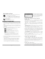
located at various positions depending on module and board type. See the
chart on page 3 of this manual to determine what features your module
offers as well as the jumper locations and ON/OFF positions.
Auto-Negotiation
The following chart states the availability of the
Auto-Negotiation
feature
on media conversion modules.
A
U T O
- N
E G O T I A T I O N O N
1 0 0 M
B P S
M
O D U L E S
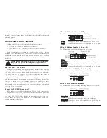
When
Auto-Negotiation
is enabled, the media converter negotiates as
a 100 Mbps Full-Duplex device; if the device the media converter is con-
nected to can operate at 100 Mbps Full-Duplex, a link will be established.
If the twisted pair port on the other device does not have the ability to auto-
negotiate, or if a 100 Mbps Half-Duplex connection is desired, Auto-
Negotiation on the media converter must be disabled. Half- and Full-
Duplex settings must be manually set and match on both end devices to
which the media converters are connected. The diagram below shows a
typical application, followed by a table with three possible configurations.
Configure
Auto-Negotiation
on
100Mbps Modules
with a 3-pin jumper block
located on the module’s PCB. Please see the diagrams and chart on pages 2-3
of this manual to verify jumper position and default setting.
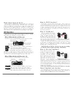
End to End Connection
Switch
TX/FX Converter
Half-Duplex
Manually Configure HDX Auto-Negotiation Off
Full-Duplex
Manually Configure FDX Auto-Negotiation Off
Full-Duplex
Auto-Negotiation On
Auto-Negotiation On
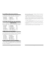
Auto-Negotiation Product Comparison
10Mbps Modules
Auto-Negotiation
Not Available
100Mbps Modules
Auto-Negotiation
DIP Switch Selectable
10/100Mbps Modules
Auto-Negotiation
Always Enabled
L
I N K
L
O S S
/ F
I B E R
A
L E R T
C
O M P A R I S O N
T
A B L E
Feature
Fault Location
Disabled LEDs
Enable At:
FX LinkLoss
Fiber
Twisted Pair
Main Site Only
TX LinkLoss
Twisted Pair
Fiber
Remote Site Only
FiberAlert
Fiber
Fiber
Remote Site Only
A
U T O
- N
E G O T I A T I O N O N
1 0 / 1 0 0 S
W I T C H I N G
M
O D U L E S
Auto-Negotiation
is a standard feature on
10/100 Switching Modules
. The
fiber port always operates at 100 Mbps FDX; the copper port auto-senses the
connected device’s speed and duplex mode: 10 Mbps or 100 Mbps and
HDX or FDX (including Flow Control).
NOTE: This module is a Plug-And-Play device, therefore Auto-Negotiation is always enabled.
Installing Media Conversion Modules
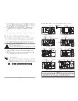
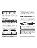
You can install media conversion modules in any available slot in a
Media
Converter
chassis. Media conversion modules are hot-swappable.
Media conversion modules ship with brackets for securing them to the
Media Converter
chassis. To install a module, simply unscrew the blank
bracket covering the slot where you will install the module. Slide the module
into the chassis, via the cardguides, until the module is seated securely in the
connector, screw in the bracket supplied with the module, then connect the
cables.
I
N S T A L L A T I O N
T
I P
Since single-strand fiber products use optics that transmit and receive on two
different wavelengths, you must deploy single-strand fiber products in pairs, or
connect two compatible Black Box single-strand fiber products. For example, connect
Compact Media Converter, TX/SSFX-SM1310-SC
(which has 1310 xmt and 1550 rcv) to a
product which has 1550 xmt and 1310 rcv, e.g.
100 Mbps TX/SSFX-SM1550-SC Module
.
The two connected products must also have the same speed and distance capabilities
(i.e. both are single-mode [20km] or both are single/PLUS [40km]).
N O T E
Media Converter
chassis ship with all but one media conversion module slot cov-
ered with “blank” brackets. Be sure to keep unused slots covered for EMI con-
tainment. It is a good idea to save any “blanks” removed during installation for
future use if configuration requirements change.

