CITYLIGHT FIBRE CHANNEL CARD
17
3)
Push the CityLIGHT Fibre Channel Card along the card guides into
the slot until it engages with the connector inside the CityLIGHT
chassis.
4)
Tighten the two captive screws on the front panel of both CityLIGHT
Fibre Channel Cards to secure them in position.
5)
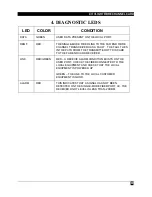
Make sure the Rx Alarm LED and Link LED on the front panel of both
CityLIGHT Fibre Channel Cards illuminate.
6)
Using the loss set, and ideally a technician at either end of the link,
check that the link budget is less than 18dB for the short haul unit or
20dB for the long haul unit.
7)
VERY IMPORTANT: Thoroughly clean the connectors using pure
alcohol and lint-free materials. Allow to air dry or blow with clean
compressed air. Never blow dry using breath. If available fiber
cleaning tape may be used.
8)
Connect the fiber cables to the Tx connectors at both ends of the link.
9)
Measure the received light level at the far end of the link. Check that
the received light level is between -6dBm and -20dBm. If the received
light level is greater than -6dBm an attenuator is required.
10) Connect the fiber cable to the receiver (Rx connector). Make sure the
Single-mode Alarm LED is extinguished, see Section 4, Diagnostic
LEDs. If the Alarm LED is illuminated, check that the receive power is
greater than -20dBm. If it is less than -20dBm check the launch
power of the far end device and that the fiber connections are correctly
made Tx to Rx.
11) Power up the local user equipment and make sure the Link LED is
green indicating that the link to the connected Fibre Channel port is
now active. If the Link LED remains red, check that the receive power
at the user port is greater than -17dBm. If it is less than -17dBm,
check the launch power of the connected device. Check the fiber
connections are correctly made Tx to Rx.
NOTE:
The receive power figures detailed above are for the 850nm
multimode version. For the 1300nm single-mode version, receive
power must be greater than -19dBm.
12) Once the link is correctly inserted, check the following:
i)
The Link LED is green.
ii) The Rem F LED is extinguished.
iii) The Alarm LED is extinguished.

