background image

BLACK BOX

®

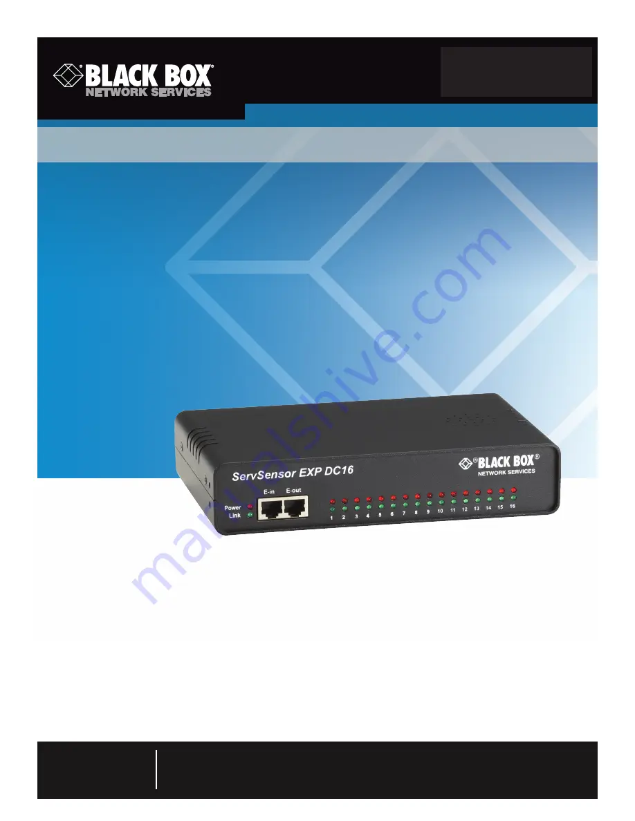
Adds 16 opto-isolated dry contacts,  

so you can monitor more data points  

from a ServSensor V4E.

ServSensor EXP DC16

March 2010 

EME1DC16

Order toll-free in the U.S.: Call 877-877-BBOX (outside U.S. call 724-746-5500) •

FREE technical support 24 hours a day, 7 days a week: Call 724-746-5500 or fax 724-746-0746 •

Mailing address: Black Box Corporation, 1000 Park Drive, Lawrence, PA 15055-1018 •

Web site: www.blackbox.com   •   E-mail: [email protected]

Customer 

Support 

Information

Содержание EME1DC16

Страница 1: ...0 EME1DC16 Order toll free in the U S Call 877 877 BBOX outside U S call 724 746 5500 FREE technical support 24 hours a day 7 days a week Call 724 746 5500 or fax 724 746 0746 Mailing address Black Bo...

Страница 2: ...at 724 746 5500 or go to blackbox com and click on Talk to Black Box You ll be live with one of our technical experts in less than 20 seconds Trademarks Used in this Manual Black Box and the Double D...

Страница 3: ...en the equipment is operated in a commercial environment Operation of this equipment in a residential area is likely to cause interference in which case the user at his own expense will be required to...

Страница 4: ...idan el flujo de aire por los orificios de ventilaci n 10 El equipo el ctrico deber ser situado fuera del alcance de fuentes de calor como radiadores registros de calor estufas u otros aparatos incluy...

Страница 5: ...on 7 2 2 What s Included 7 2 3 Hardware Description 8 2 3 1 Front Panel 8 2 3 2 Back Panel 9 3 Installation 10 3 1 Connecting to the Base Unit 10 3 2 Setting Up a Sensor Standard Configuration 11 3 3...

Страница 6: ...0 000 hours Network Interface 1 standard 10 100BASE T Ethernet RJ 45 port Connectors Input 16 2 wire dry contact inputs configured as opto isolated 2 wire dry contact inputs support up to 50 VDC and 8...

Страница 7: ...ted dry contacts This increases the number of data points that can be monitoried from a single ServSensor V4E 2 2 What s Included Your ServSensor EXP DC16 package should contain the following items If...

Страница 8: ...16 indicate the connectivity status of the sensors connected to each port These LEDs also indicate system status during various operations Table 2 2 Status Online LED functions Function Description U...

Страница 9: ...panel and Table 2 3 describes its components 5 6 Figure 2 2 Back panel Table 2 3 Back panel components Number Component Description 5 16 2 pin ports The 2 pin dry contact ports numbered 1 16 are used...

Страница 10: ...low 1 Connect the cable to your chosen port See Figure 3 1 Figure 3 1 E1 port 2 Connect the other end to the E in port See Figure 3 2 Figure 3 2 E in port NOTE Make sure that the 7 5 volt power supply...

Страница 11: ...uration It focuses on the dry contact sensor however this basic setup process applies to all compatible sensors If you require information on specific functions of a particular sensor then download th...

Страница 12: ...with its current reading and status 4 Click on the dry contact sensor s name indicated in previous screen The Sensors page appears Figure 3 7 Sensors page NOTE You can also access this page by clicki...

Страница 13: ...sensor icon or another type of sensor icon 7 The page shown in Figure 3 9 appears Figure 3 9 Sensor Settings page As with the ServSensor V4E the procedure for changing sensor values remains the same...

Страница 14: ...mpatible sensors If you require information on specific functions of a particular sensor then download the manual for that sensor from our Web site or locate it on your product CD Connect the two modu...

Страница 15: ...is example we will use Port 1 Figure 3 12 Plug sensor into Port 1 5 After the unit is connected access your Web interface type the desired IP address into your browser and log in and navigate to the s...

Страница 16: ...Page 16 ServSensor EXP DC16 Figure 3 14 Sensors page 7 Click on any available sensor icon see Figure 3 15 The settings for that particular sensor will appear as shown in Figure 3 16 Figure 3 15 Temper...

Страница 17: ...724 746 5500 blackbox com Page 17 Chapter 3 Installation Figure 3 16 Sensor Settings page...

Страница 18: ...sholds This allows you to determine how you will be notified that a sensor s reading has reached the specified parameters high warning critical etc 4 1 Adding a Notification 1 Login as the administrat...

Страница 19: ...cations do refer to the separate notification manuals on your product CD 4 2 SNMP Traps Set up a notification via SNMP trap so that when your sensor reaches a certain threshold it will send a notifica...

Страница 20: ...er trap or click the Next button The screen shown in Figure 4 4 appears Figure 4 4 SNMP Trap Notification screen 8 Enter the Maximum Times to Resend and the Resend Intervals secs These parameters set...

Страница 21: ...ion board and sensor 11 Select the status and the action Figure 4 6 Selecting setting and trap name NOTE In the example above the SNMP trap is bound to the temperature sensor that s connected on Port...

Страница 22: ...e 22 ServSensor EXP DC16 12 Once we have created the parameters for the SNMP trap we need to make it active To do this go back to the Notification tab It should look like the screen shown in Figure 4...

Страница 23: ...SNMP trap parameters as before Figures 4 8 and 4 9 appear Select the expansion board then select the sensor Figure 4 8 Select the expansion board then select the sensor 14 Select the status then selec...

Страница 24: ...NMP trap has been added to the Notification page Figure 4 10 Notification page NOTE To remove this trap and make it inactive highlight the notification and click remove NOTE You can repeat this proces...

Страница 25: ...g from cabinets and racks and power and surge protection products to media converters and Ethernet switches all supported by free live 24 7 Tech support available in 20 seconds or less Copyright 2010...

Отзывы: