CITYLIGHT 10/100 ETHERNET TRANSCEIVER CARD
19
9)
Using the loss set, and ideally a technician at the CityLIGHT remote
chassis, check that the link budget is less than 18 dB for the standard-
power unit or 25 dB for the high-power unit.
10)
Ensure connector ends are clean. Connect the fiber cables to the Rx and
Tx connectors at both ends of the link. Make sure that the local transmit
is connected to the far end receive and vice versa.
11)
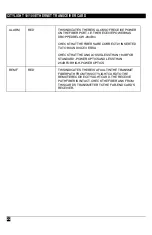
Make sure the Alarm LED is extinguished. If the Alarm LED on the
CityLIGHT 10/100 Ethernet Transceiver in the CityLIGHT managed
chassis remains illuminated, check that the receive power is greater
than -28 dBm. If it is less than -28 dBm, check the launch power of the
CityLIGHT 10/100 Ethernet Transceiver in the CityLIGHT remote
chassis and check the fiber connections are correctly made Tx to Rx.
12)
If the Alarm LED on the CityLIGHT 10/100 Ethernet Transceiver in the
remote chassis remains illuminated, check that the receive power is
greater than -28 dBm. If it is less than -28 dBm, check the launch power
of the CityLIGHT 10/100 Ethernet Transceiver in the CityLIGHT
managed chassis.
13)
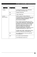
At both CityLIGHT Fiber Extender Modules insert the copper interface in
the RJ 45 10T/100TX port. To connect to a DCE, use a straight-through
cable; to connect to a DTE, use the crossover cable supplied. Make sure
the Link LED illuminates.
14)
Once the link is correctly made, check the following:
i)
The 100 LED is illuminated and is the correct color at both ends of
the link.
ii)
The Link LED is illuminated.
iii)
The Rem F LED is extinguished.
iv)
The Alarm LED is extinguished.
v)
The Data LED flashes (if the link is active).
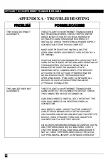
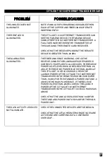
If any of the LEDs is not correctly illuminated/extinguished, see
Appendix A – Troubleshooting for possible causes.
NOTE:
During commissioning most faults are associated with bad/wrong
cabling, incorrect patching, loss of power, or excessive power budget.


