CB-100-1
6
3.1
Modularer Aufbau des VARIPACK
Frequenzumrichters
2
1
3
4
5
6
7
8
9
5a
10
11
5b
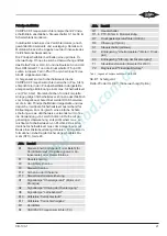
Abb. 1: Modularer Aufbau VARIPACK Frequenzumrichter
1
Leistungsteil
2
Kühlkörper
3
Obere Gehäuseabdeckung
4
Untere Gehäuseabdeckung
5
Steuermodul mit
5a: Klemmleiste
5b: Steckplatz für SD-Karte
6
Erweiterungsbausatz zur Druckregelung
(Option)
7
Schnittstellenerweiterung mit Echtzeituhr
8
Steuermodulabdeckung
9
Abnehmbares Bedienteil mit Display und
Tastenfeld (Option)
10+11
Befestigungsbleche
Содержание VARIPACK FDU+12
Страница 12: ...CB 100 1 12 1 2 3 4 Abb 7 Steuremodul abmontieren...
Страница 46: ...CB 100 1 46 1 2 3 4 Fig 7 Dismounting the control module...
Страница 64: ...CB 100 1 64 Fig 17 Graphical representation of the general control functions of the extension module...
Страница 70: ...Notes...
Страница 71: ...Notes...


