KB-130-6
23
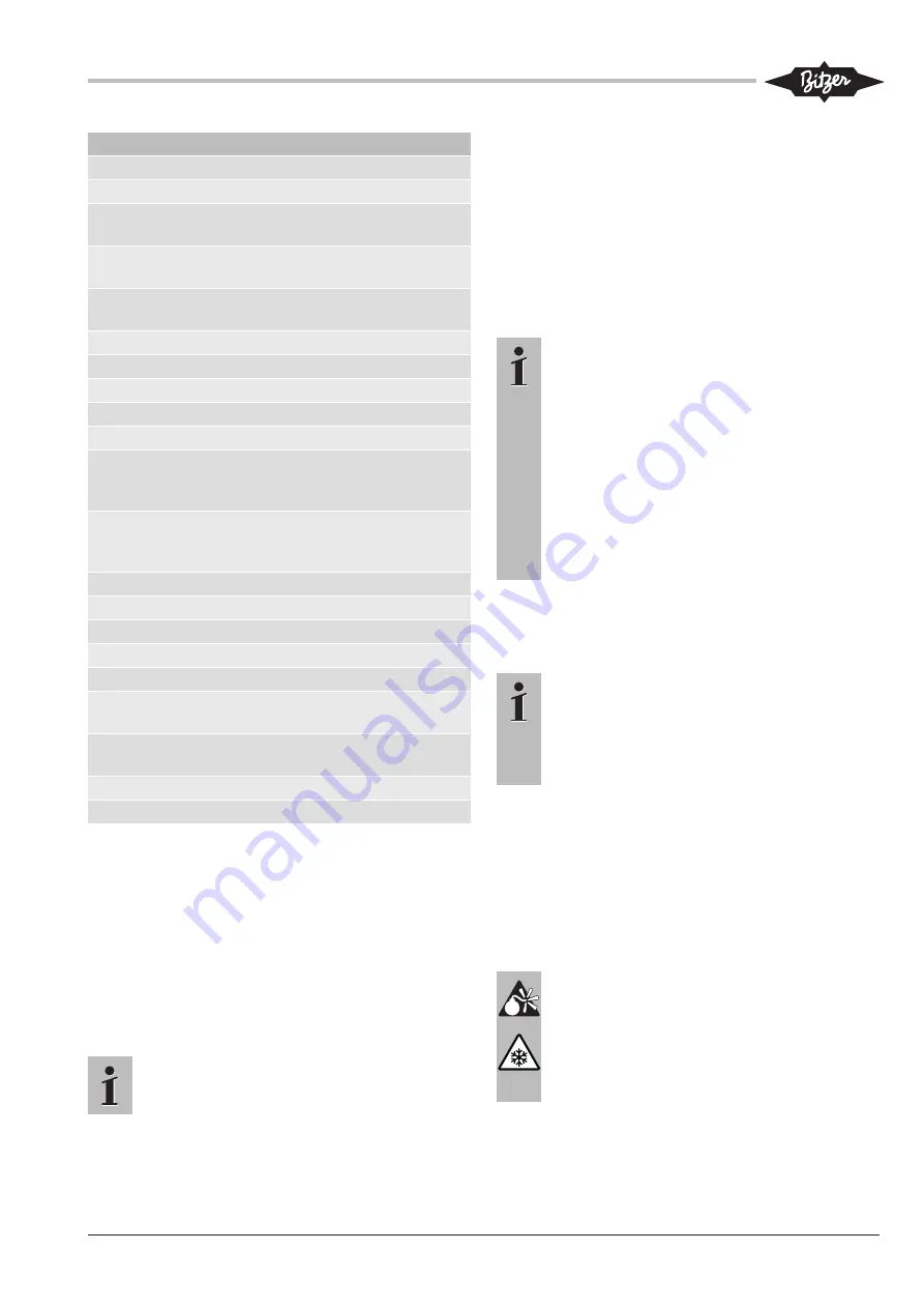
Connection positions
8
Oil return (oil separator)
8*
Oil return for NH
3
with insoluble oil
9
Connection for oil and gas equalisation
(parallel operation)
9a
Connection for gas equalisation (parallel
operation)
9b
Connection for oil equalisation (parallel op-
eration)
10
Connection for oil heating
11
Oil pressure conn
12
Oil pressure connection -
13
Cooling-water connection
14
Intermediate pressure connection (MP)
15
Refrigerant injection (operation without re-
frigerant subcooler and with thermostatic
expansion valve)
16
Connection for oil monitoring (opto-elec-
tronic oil monitoring device "OLC-K1" or oil
differential pressure switch "Delta-PII")
17
Refrigerant inlet on the subcooler
18
Refrigerant outlet on the subcooler
19
Clamping area
20
Terminal plate
21
Connection for oil service valve
22
Pressure relief valve to the atmosphere
(pressure side)
23
Pressure relief valve to the atmosphere
(suction side)
SL
Suction gas line
DL
Discharge gas line
Tab. 5: Connection positions
Dimensions (if specified) may have tolerances accord-
ing to EN ISO 13920-B.
The legend applies to all BITZER reciprocating com-
pressors and includes connection positions which are
not used for all compressor models.
5 Commissioning
Information
General information and requirements, see op-
erating instructions KB-104.
Prior to putting the system into operation, check all
safety and monitoring devices of the system and in the
machine room for correct function.
The following information must also be available:
• Construction data.
• Maximal admissible pressures at standstill and dur-
ing operation.
• Pipelines and instruments diagram.
Information
Special care is required when commissioning
CO
2
compressors for transcritical applications.
Due to the high solubility of refrigerant in oil, the
high pressure levels and strong pressure vari-
ations after the starting process, overload and
lack of lubrication may occur.
It is therefore necessary to observe thoroughly
the working behaviour and the operating condi-
tions and to switch off the compressor(s) tem-
porarily in case of abnormal conditions.
Supervise the system during the whole commis-
sioning process!
5.1
Evacuation
• Switch on the oil heater.
Information
For applications with CO
2
, the "standing va-
cuum" should reach a value of 0.67 mbar
(500 microns) before the commissioning.
During the evacuation process, break the va-
cuum several times with dry nitrogen.
5.2
Charging refrigerant
The following chapter describes general requirements
when filling with refrigerant and the commissioning of
the compressors. Depending on the version and the
control system of the plant (e.g. for systems with inter-
mediate pressure receivers or booster), some adapta-
tions may be necessary.
Danger!
Liquid CO
2
evaporates quickly, cools down at
the same time and forms dry ice!
Danger of cold burns and frost bites!
Avoid uncontrolled deflating of CO
2
!
When filling the system with CO
2
, wear gloves
and goggles!
• When extracting CO
2
out of a bottle without ascend-
ing pipe, use a pressure reducer! In general, also
Содержание 2KTE-7K
Страница 43: ...Notes...


