background image

27


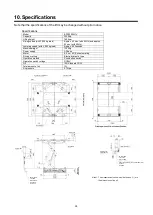
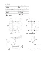
Specifications 

Model 

BSC3200KV (fitted with optional storage 
box) 

Capacity 

3200Kg 

Lifting height 

1800mm 

Rising speed (with 3,000 kg load) 

Approx. 43 sec. (with 60Hz) and approx. 
52 sec. (with 50Hz) 

Lowering speed (with 3,000 kg load) 

Approx. 40 Seconds 

Machine weight 

1350Kg 

Power supply 

3-Phase  

Motor 

2. 2 kw, 4P, 5 minutes rating 

Driving method 

Electro-hydraulic type 

Operation method 

Push-button switch 

Operating voltage 

DC24V 

Oil 

ISO Standard VG32 

Total hydraulic pressure 

13L 

Air pressure 

0.7Mpa 


Lift (right side)


D

riv

e i

di

rec
tion


Slide


Slide


Note 1: The measurements shown inside the box (

) are 

the dimensions of the pit.


Drawing when Lift is at Lowest Position


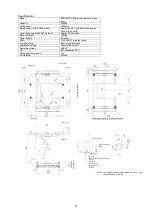
Lift (left side)


Swing arm


Supporter


(M

ac

hi

ne


di

m

ens

ions

)


Storage box


Pressure gauge


4-point push-button 
switch


33 or


mo

re


 LS cable 

 Power supply cable (procured locally) 

 Air hose 

 Air hose B 

 Overflow tube B 


 High-pressure hose 

 Air tube C


Draining port
 

Содержание BSC3200 Series

Страница 1: ...n manual with care and promptly request for a copy if it becomes lost If the operation manual is not for the actual lift request for a correct copy with the retailer from whom the product was purchase...

Страница 2: ...ion and incorrect collating In this manual Danger Warning Caution are defined and specified as below Notice of Warnings are very important for safe operations As these are very important to protect op...

Страница 3: ...5 7 1 Preparation for Vehicle Entry 15 7 2 Vehicle Entry 15 7 3 Set Up Lifting Point 15 7 4 Lifting Operation 17 7 5 During Work 17 7 6 Lowering Operation 18 7 7 Vehicle Exit 18 7 8 Clean Up after Ser...

Страница 4: ...f Warnings are very important for safe operations As these are very important to protect operators from accident resulting in injury or death or damage to properties make certain to understand them fu...

Страница 5: ...and attaching parts The partial lifting only on front or back as well as on left or right is strictly prohibited The vehicle may potentially fall or become deformed There is also a risk of lift becom...

Страница 6: ...parts or with vibration it may result is falling of the vehicle and damage to the vehicle KEEP FEET FREE from lift and vehicle when operating lift It may result in pinching feet or serious injury DO N...

Страница 7: ...any vehicle that exceeds the maximum capacity of the lift 4 Do not lift a vehicle with people or cargo still on board 5 Make sure there is no oil or soil on supporter when raising a vehicle 6 Stop lif...

Страница 8: ...Others 1 Do not modify the lift in any way Doing so can prevent the lift from performing sufficient functions which may potentially lead to a serious accident 2 Do not use any supports other than genu...

Страница 9: ...personal accidents and property damages as well as capacity of the lift Purchase and apply these labels promptly when they become worn damaged or peeled off while the lift is used Center of Gravity Po...

Страница 10: ...Control box Filter regulator Arm pit cover Built in hydraulic unit Cylinder Sliding supporter Arm pit cover Separately installed hydraulic unit Push button control switch Filter regulator Cylinder Sli...

Страница 11: ...ms to be stored Down button can only be used when the lift at the lowest lowered position The Up and Down buttons cannot be operated at the same time The lengths of sliding supporters can be adjusted...

Страница 12: ...ire arms can be stored inside the pit by retracting the swing arms to the MIN position Can be used for ordinary passenger vehicles that are lifted with side sills Features the function to reduce press...

Страница 13: ...l flow in case sudden flow of oil from cylinder due to the breakage of hydraulic circuit etc Relief valve In case of below it would work to prevent lift from break a lifting heavier load than lift s c...

Страница 14: ...ing Perform visual and auditory checks while performing the full stroke operation of the lift and arms with no vehicle loaded Contact the lift supplier from whom the product was purchased if any abnor...

Страница 15: ...of the filter regulator Drain method Push up the draining valve Water sprays out with air The appropriate value of the pressure of air primary side pressure supplied to the filter regulator is betwee...

Страница 16: ...icle and may potentially damage the vehicle or the lift if the lift is not lowered to the lowest position with swing arms stored Set the center of gravity of the vehicle to within the range specified...

Страница 17: ...of each supporter so that the load is distributed evenly on each supporter Raise swing arms only when the lift unit is at the lowest lowered position Always make sure that the rubber pads contact fla...

Страница 18: ...he verification again Do not lift the vehicle if the balance cannot be improved Raise the vehicle to the vehicle servicing height if the vehicle is balanced well Once the vehicle is raised to the top...

Страница 19: ...lift to the lowest position Never stand under the vehicle while operating the lift Lowering the lift with transmission jack rod or the like for removing or installing parts still attached to the vehi...

Страница 20: ...de the lift area to clean In the event any abnormality is discovered on such occasion consult the lift supplier immediately Lower the lift to the lowest position and shut off the power supply circuit...

Страница 21: ...ng sounds when raised 8 3 Air circuit Couplings and air tubes Verify to ensure there are no cracks or air leaks Control panel Electrical components magnet switch relay etc Verify to ensure they are op...

Страница 22: ...points described below Cylinder upper edge 2 locations grease Tab shaft part 2 locations grease Slide Plate Sliding roller shaft and roller parts specified grease Cylinder support pivot point 2 locati...

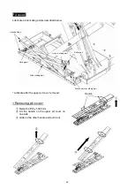
Страница 23: ...upper pit cover removed Removing pit cover Raise the lift by 1 000 mm Lift the handle on the upper pit cover on one side Grab on the other handle and pull it out Link shaft part Link pin sliding part...

Страница 24: ...ic oil Replenish hydraulic oil Foreign matter is contacting the shoe under the lower part of the link Remove the foreign matter The lift cannot be lowered A lowering stop hook is caught on the rack Ra...

Страница 25: ...ectro hydraulic type Operation method Push button switch Operation switch voltage DC24V Oil ISO Standard VG32 Total amount of oil 13L Air pressure 0 7Mpa Hydraulic unit built in Lift right side Slide...

Страница 26: ...tion method Push button switch Operation switch voltage DC24V Oil ISO Standard VG32 Total hydraulic pressure 13L Air pressure 0 7Mpa Drive in direction Note 1 The measurements shown inside the box are...

Страница 27: ...thod Push button switch Operating voltage DC24V Oil ISO Standard VG32 Total hydraulic pressure 13L Air pressure 0 7Mpa Lift right side Drive in direction Slide Slide Note 1 The measurements shown insi...

Страница 28: ...lic type Operation method Push button switch Operating voltage DC24V Oil ISO Standard VG32 Total hydraulic pressure 13L Air pressure 0 7Mpa Lift right side Drive in direction Slide Slide Note 1 The me...

Страница 29: ...lowering button Ry Latching relay S0L1 Selex pneumatic valve hook release SOLA Selex pneumatic valve arm raising SOL2 Lowering valve LS1 Hook release detection LS LS Lift lower limit detection LS Hyd...

Страница 30: ...ydraulic oils to dispose of the lift Scrap method especially disposal of operation oil is obliged to be in conformity to the local law Please scrap properly according to the law If any question contac...

Страница 31: ...e damage or trouble caused by the modification that affects the originally designed functions 3 Any consumable parts that need to be replaced 4 The damage or trouble caused by natural disaster such as...

Страница 32: ...vailability of spare parts The spare parts is available for 8 years after discontinuing manufacturing Contact your supplier for any information regarding to the after service When contacting your supp...

Страница 33: ...32 Memo...

Страница 34: ...33 Memo...

Страница 35: ...34 Memo...

Страница 36: ...SUGIYASU CORPORATION 3 21 4 CHOME HONGO CHO TAKAHAMA CITY AICHI JAPAN 444 1394 TEL 81 0 566 53 1126 FAX 81 0 566 53 1844 http www bishamon co jp en...

Отзывы: