background image

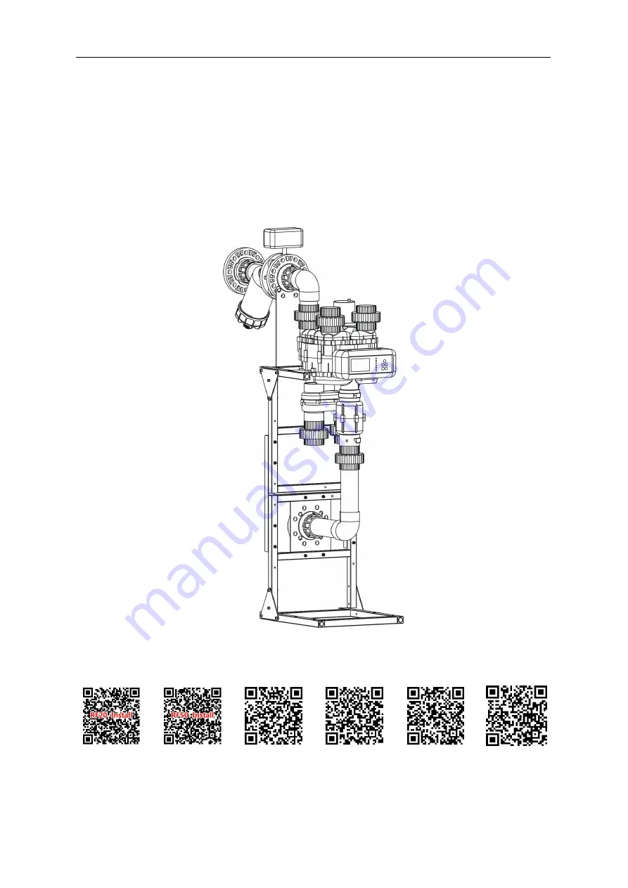
RF20/RF50 two tank soften valve manual

RF20

RF50

RF Side-loading soften Valve

Direction for Installation & Usage

RF20

Install animation

RF50

Install animation

RF Shifting

animation

Brine absorb and

refill animation

Meter and electric

valve repair

Flow process

animation

Содержание 20-25

Страница 1: ...nual RF20 RF50 RF Side loading soften Valve Direction for Installation Usage RF20 Install animation RF50 Install animation RF Shifting animation Brine absorb and refill animation Meter and electric va...

Страница 2: ...RF20 RF50 two tank soften valve manual Controller Handling Instruction picture 1 Controller Front Panel...

Страница 3: ...Right regenerate start position click button the time mode and flow mode to switch between displays 7 Shift Unlock state according to to go directly to the next station Equipment through the operation...

Страница 4: ...5 Positioning Positioning signal socket 5 pin the valve switching control signal in place to stop 6 Start station Start position signal socket 5 holes spool position control signal 7 Motor Electrical...

Страница 5: ...RF20 RF50 two tank soften valve manual Picture 4 RF50 pipe install Picture 5 Controller and valve connection...

Страница 6: ...RF20 RF50 two tank soften valve manual Picture 6 RF20 IN OUT pipe install Picture 7 RF50 IN OUT pipe install...

Страница 7: ...d valve closed the controller shows that water is full This output is 12 v active signal can not access to high voltage circuit Picture 8 directly signal from lever switch Picture 9 lever switch B Sin...

Страница 8: ...d the hardness of raw water Exchange tank Top bottom4 8UN NO D Effective vertical height 2 450 1368 2 500 1636 2 600 1636 2 750 1600 2 450 1650 2 600 1800 2 600 1800 2 750 1800 2 500 2000 2 600 2200 2...

Страница 9: ...ter hardness mmol L 720 raw water hardness mmol L Period salt water volume L 150 230 288 Cleaning time minute 30 40 50 Notes 1 Typically the equipment running with flow mode but the time parameters of...

Страница 10: ...alt open the bottom of salt under the sewage outfall discharge of salt water tank bottom sediment sludge 3 Clean the filter regularly to prevent water blockage cause the device to reduce the work pres...

Страница 11: ...as wash tank 1 Turn off the device inlet valve a device to Deputy tank water left the main tank cleaning right 2 Demolition of the left pipe and the exchange of tank water distributor 3 Remove from th...

Страница 12: ...sion space Resin layer Resin body wash mop Resin body wash mop Picture16 Resin scrub 3 Clean water ejector and its component When the regeneration station do not absorb salt do not feed water they may...

Страница 13: ...Installation maintenance user s guide for RF Floating bed Control Valve 13 Picture18 multiple valve drive schematic Picture19 Main valve exploded view...

Страница 14: ...e side on the uper valve body starting work stations direction 3 Install the valve core the first guarantee positioning magnets and groove on FIG 26 3 the valve core hole and let a pair of valve insta...

Страница 15: ...off inlet pressure release To the next station the station is not a starting station Detect the positioning signal motor stop motor rotating Delay seconds Solenoid valve or motorizedvalve off The cur...

Страница 16: ...Installation maintenance user s guide for RF Floating bed Control Valve 16 Picture 24 RF20 Flow pressure curve Picture 25 RF50 Flow pressure curve...

Страница 17: ...Installation maintenance user s guide for RF Floating bed Control Valve 17 Picture 26 RF Brine flow pressure curve...

Страница 18: ...Installation maintenance user s guide for RF Floating bed Control Valve 18...

Отзывы: