Waterproof Audio System
Installation Manual
2300 Pioneer Ave. Rice Lake, WI 54868
Phone: 888-BIG-BIKE 715-234-3336
Fax: 715-234-6872
Email: [email protected]
Website: www.bigbikeparts.com
CONTENTS
1. Introduction ………………………………………………...……………………………………………….2
2. Applications …………………………………………………………………………………………………2
3. Safety Precautions……………………………………………………………………………………….....2
4. Specifications………………………...……………………………………………………………………...2
5. Parts List ….……………………………………………………………………………………………..…..2
6. Select the best location for mounting …………………………………………………………………….2
7. Amplifier Installation……….. ……………………………...…………………………………………….…3
8. Speaker Installation………….…. …………………………………………………………………….……3
9. Amplifier Functional Test ………………………..……………………………………………………….…4
Motorcycle / ATV Specialized Outdoor Audio System
Scan code with
your smartphone to
view demo video.
9. Amplifier Functional Test
We suggest the following product testing procedures to test the amplifier for the first time. The automatic on/off system could help to save
electricity in various situations. The LED light indicates the status of the amplifier. It is only switched on if the amplifier is turned on.
The amplifier would be turned on automatically in the following situations:
1) Connect the audio device (e.g. MP3 player) to the amplifier with the 3.5 mm Stereo Male to Male cord. Turn the volume control towards 10
o’clock position and play any music. The LED light should be switched on and the amplifier should come to life immediately.
2) If the music device is already playing, connecting it to the amplifier should also turn on the amplifier automatically.
The amplifier would be turned off automatically in the following situations:
1) While the music is still playing and the volume is adjusted to the minimal for more than 40 seconds, the amplifier should turn off spontaneously.
2) If the music stops playing while the audio device is still connected to the amplifier, the amplifier would also turn off automatically after 40
seconds.
3) Disconnecting the audio device from the amplifier would turn off the amplifier after 40 seconds.
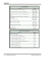
Item Qty Description
A
1 Amplifier
B
1 Amplifier bracket
C
1 Volume control
D
1 Volume control clamp
E
2 High fidelity speakers
F
2 Brackets (surface mount)
G
2 Clamps (handle bar mount) 1” and 7/8”
H
4 Twin adhesive sticker
I
2 Speaker holders
J
2 Stainless steel brackets
K
2 Pan head, Phillips, type C, 4x15 mm
L
2 Pan head, Phillips, type C, 4x25 mm
M
4 Speaker nuts, 4x7mm
N
6 Pan head, Phillips, type A, 4x12 mm
Model 13-250A, 13-250BK, etc.
Item Qty Description
O
2 Truss head, Phillips, type C, M4x8 mm
P
2
Hex nuts 4.85x3.8 mm
Q
2 Lock washers 6.3x10 mm
R
2 Lock washers 5.8x10 mm
S
4 Flat washers 6.3x10 mm
T
2 Square head bolts, 4.85x10 mm
U
2 Hex point, type A, 6.3x19 mm
V
2 Truss head, Phillips, type B, 4x13 mm, spare for plastic mount.
W
3 C-ring EPDM gasket, 50Lx15Wx1.5H mm
X
3 C-ring EPDM gasket, 82Lx15Wx1.5H mm
Y
1 Volume control, Pan head, Phillips, type C, 4x25 mm
Z
2 Washer 4 x 9.5 x 0.8 mm
ZZ
2 Hook and Loop
ZA
2 Nylon spacer
3) Mirror side:
1. Select mounting bracket I and J from the package and disassemble the side mirror.
2. Select the appropriate mounting style of the bracket. To position the speakers at a
higher level see diagram A; to position the speakers at a lower level see diagram B.
3. Hold the speaker in position and secure the mounting to the holder with a screw
(4×15 mm) and a nut.
4. Screw the holder to the stainless steel bracket with a 4×6 mm screw
and adjust the angle.
5. Reassemble the side mirror on the stainless steel bracket as shown.
6. Secure a tight mount to prevent detachment of the bracket or the mirror.
7. Adjust the final projecting angle of the speaker.
8. Check for any loose screws and nuts.
A
B


