background image

Installation, Operation and Maintenance Manual 

MAN 564 Rev. 6

June 2020

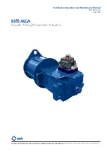
Biffi ALGA 

Double-Acting Pneumatic Actuator

Copyright © Biffi. The information in this document is subject to change without notice. Updated data sheets can be obtained from our website www.biffi.it or from your nearest Biffi Center: 


Biffi Italia s.r.l. - Strada Biffi 165, 29017 Fiorenzuola d'Arda (PC) –

 Italy PH: 

+39 0523 944 411 – [email protected]

Содержание ALGA Series

Страница 1: ... Actuator Copyright Biffi The information in this document is subject to change without notice Updated data sheets can be obtained from our website www biffi it or from your nearest Biffi Center Biffi Italia s r l Strada Biffi 165 29017 Fiorenzuola d Arda PC Italy PH 39 0523 944 411 biffi_italia biffi it ...

Страница 2: ...ed 6 June 2020 General update Migration to new template 5 March 2018 Revised Data plate Ermanni Orefici Vigliano 4 April 2016 Updated Applicable Regulation Section 1 1 1 Ermanni Orefici Vigliano 3 April 2013 Revised Section 5 1 1 Ermanni Stoto Vigliano 2 January 2011 Revised Sectional Dwg Ermanni Stoto Vigliano 1 November 2010 General Update Ermanni Stoto Vigliano ...

Страница 3: ...on Actuator Receipt 4 2 2 Actuator Handling 4 2 3 Storage 7 2 4 Actuator Assembly on the Valve 7 2 4 1 Types of Assembly 7 2 4 2 Assembly Procedure 16 2 5 Pneumatic Connections 17 2 6 Electrical Connections If Any 18 2 7 Commissioning 19 Section 3 Operation and Use 3 1 Operation Description 20 3 2 Residual risks 27 3 3 Calibration of the Angular Stroke 27 3 4 Calibration of Micro switches 34 3 5 C...

Страница 4: ...e 41 5 2 1 Replacement of Cylinder Seals 41 5 3 MHP Hydraulic Manual Override Maintenance and Troubleshooting 49 5 3 1 Operation 49 5 3 2 Manual Operation 49 5 3 3 Remote Operation 49 5 3 4 Setting 50 5 4 Lubrication of Mechanism 53 5 5 Dismantling and Demolition 54 Section 6 Troubleshooting 6 1 Failure or Breakdown Research 55 Section 7 Layouts 7 1 Spare Parts Order 56 7 2 Parts List for Maintena...

Страница 5: ...014 35 EU Directive for low voltage equipment 2014 30 EU Directive for the electromagnetic compatibility 2014 34 EU Directive and safety instructions for use in hazardous area 1 1 2 Terms and Conditions Biffi Italia s r l guarantees that all the items produced are free of defects in workmanship and manufacturing materials and meet relevant current specifications provided they are installed used an...

Страница 6: ...or operation The angular stroke of the yoke is adjustable between 82 and 98 by means of the external mechanical stops screwed into the left wall of the mechanism housing and into the end flange of the pneumatic cylinder The cover of the scotch yoke mechanism is arranged for the assembly of the required accessories positioner signalling limit switches position transducer etc by means of proper matc...

Страница 7: ...100 C Optional from 60 C to 200 C Supply pressure Please refer to technical document actuator data sheet Output torque Up to 750000 Nm higher value with special version Manual handpump MHP optional Control system optional Valve coupling Pneumatic cylinder Valve position indicator Scotch yoke mechanism Hydraulic cylinder for ALGA MHP models or second pneumatic cylinder for ALGA 2 double cylinder mo...

Страница 8: ...ngs have already been made at the factory If the actuator is delivered separately from the valve it is necessary to check and if required to adjust the settings of the mechanical stops Section 3 4 and of micro switches if any Section 3 5 2 2 Actuator Handling NOTICE The lifting and handling should be made by qualified staff and in compliance with the laws and provisions in force WARNING The fasten...

Страница 9: ...LGA MHP ALGA MSJ actuators Figure 5 Lifting points for ALGA ALGA MHP ALGA MSJ actuators 1 Point of support 2 Supports for lateral positioning 3 Don t lay the actuator on tie rods of cylinder s and don t lay the actuator on accessories manual handpump manual jackscrew pneumatic control group etc 1 2 Lifting points obligatory 3 Balancing point ...

Страница 10: ...he ropes to prevent the load shifting sideways in an uncontrolled manner Use slings of such length that the angles of the leg from vertical are as narrow as possible αMAX 20 During handling do not transport the suspended actuator above staff members in charge of the operation WARNING Do not use the lifting eyelets on actuator to lift valve actuator assembly WARNING Any lifting method different fro...

Страница 11: ... perfect tightness Coat with oil grease or protection disc the valve coupling area Periodically operate the actuator Section 3 3 2 4 Actuator Assembly on the Valve 2 4 1 Types of Assembly For coupling to the valve the housing is provided with a flange with threaded holes according to Biffi standard tables SCN6200 SCN6200 1 SCN6201 SCN6201 1 SCN6201 3 SCN6201 5 The number dimensions and diameter of...

Страница 12: ... with keyways for coupling to the valve stem the dimensions of which are according to Biffi standard tables SCN6200 and SCN6201 N threaded holes PCD holes number and size according to ISO 5211 Flow line Top view of the Scotch yoke mechanism actuator shown in closed position Drive sleeve Table 1 Dimensions mm Actuator model ød1 ød3 ød4 øM N P h1 H max W K X Figure 7 ...

Страница 13: ...peration and Maintenance Manual MAN 564 Rev 6 June 2020 Installation Section 2 Installation N threaded holes PCD number and size according to ISO 5211 but the holes are on centerline instead of straddle the centerline Flow line Top view of the Scotch yoke mechanism actuator shown in closed position N 4 holes flange N 8 holes flange Drive sleeve Table 2 Dimensions mm Actuator model ød1 ød2 ød3 ød4 ...

Страница 14: ...564 Rev 6 June 2020 Installation Section 2 Installation N threaded holes PCD holes number and size according to ISO 5211 Flow line Top view of the Scotch yoke mechanism actuator shown in closed position Drive sleeve Table 3 Dimensions mm Actuator model ød1 ød2 ød3 ød4 N h1 h2 H max ød5 W K Figure 9 ...

Страница 15: ...400 220 50 242 8 Installation Operation and Maintenance Manual MAN 564 Rev 6 June 2020 Installation Section 2 Installation N threaded holes PCD holes number and size according to ISO 5211 Flow line Top view of the Scotch yoke mechanism actuator shown in closed position Drive sleeve Table 4 Dimensions mm Actuator model ød1 ød2 ød3 ød4 N h1 h2 H max ød5 W K Figure 10 ...

Страница 16: ...allation Operation and Maintenance Manual MAN 564 Rev 6 June 2020 Installation Section 2 Installation N threaded holes Flow line Top view of the Scotch yoke mechanism actuator shown in closed position Drive sleeve Table 5 Dimensions mm Actuator model ød1 ød2 ød3 ød4 N h1 h2 H max ød5 W K Figure 11 ...

Страница 17: ...aintenance Manual MAN 564 Rev 6 June 2020 Installation Section 2 Installation N threaded holes PCD holes number and size according to ISO 5211 Flow line Top view of the Scotch yoke mechanism actuator shown in closed position Drive sleeve Table 6 Dimensions mm Actuator model ød1 ød2 ød3 ød4 N h1 h2 H max ød5 W K Figure 12 ...

Страница 18: ...on Section 2 Installation N threaded holes PCD number and size according to ISO 5211 but the holes are on centerline instead of straddle the centerline Flow line Top view of the Scotch yoke mechanism actuator shown in closed position Drive sleeve Table 7 Dimensions mm Actuator model ød1 ød2 ød3 ød4 N h1 h2 H max ød5 W K Figure 13 ...

Страница 19: ...re can be machined by Biffi to couple the valve stem provided its dimensions match the maximum stem acceptance of the bush according to Biffi doc TN1005 The particular execution of the flange and bushing allow the actuator to be rotated by 90 in 4 different positions according to the following figure Flow line Drive sleeve Drive sleeve Snap ring Insert bush Insert bush Housing Adaptor flange N 4 h...

Страница 20: ... actuator valve coupling Operate the actuator so that it reaches the position matching valve position Section 3 3 Lubricate valve stem with oil or grease Properly clean and remove grease from coupling flange surfaces Connect if supplied separately the adjustment insert to valve stem and fasten it with the special fastening pins Lift the actuator using the special lifting points Section 2 2 Install...

Страница 21: ...perly clean the interior of pipes sending through them plenty of the supply fluid used in the system Mould and fasten the connection pipes so that no irregular strains at entries or loosening of threaded connections occur Make the connections according to the operating diagram Check the absence of leakages from pneumatic connections NOTICE If necessary to mount components not in Biffi scope of sup...

Страница 22: ...2016 2014 35 EU from 20 April 2016 2004 108 EC Directive for the electromagnetic compatibility until19 April 2016 2014 30 EU from 20 April 2016 94 9 CE Directive and safety instructions for use in hazardous Area until 19 April 2016 2014 34 EU from 20 April 2016 Remove plastic plugs from cables entries Screw firmly the cable glands Introduce connection cables Make the connections in compliance with...

Страница 23: ...dehydration are as prescribed Check that the feed voltage values of the electric components solenoid valve coils micro switches pressure switches etc are compatible with those reported on the identification plate of the actuator Figure 1 Check that the setting of the components of the actuator control unit pressure regulator pressure switches flow control valves etc meet the plant requirements Car...

Страница 24: ... cylinder chamber for example opening The cylinder piston stroke causes the actuator operation and the consequent valve movement to the operational position requested in this case to the open position Upon a demand the closing chamber the cylinder is fed by pressurized gas and at the same time the gas is discharged from the open chamber into the return line the actuator performs the closing operat...

Страница 25: ...ousing 2 Yoke 3 Yoke bushing 4 Cover 5 Guide block pin 6 Sliding block 7 Guide block 8 Guide bar 9 Guide block bushing 10 Travel stop screw 11 Cylinder head flange 12 Piston rod bushing 13 Piston rod seal ring 14 Piston rod 15 Piston 16 Piston guide sliding ring 17 Piston seal ring 18 Cylinder tube 19 End flange 20 Travel stop screw 21 Sealing washer 22 Tie rod ...

Страница 26: ...ilot spring etc The spring return control valves allow fail safe operation Pressurized air Atmospheric pressure air Manual control Pneumatic pilot control Dual solenoid control Solenoid control Figure 18 ON OFF service four way control valve For local or remote operations please refer for information only to par 3 3 1 3 3 2 3 3 3 and 3 3 4 and prior to technical documentation furnished with actuat...

Страница 27: ...ator in the fail safe condition When the gas supply pressure drops below the pressure switch 5 set point the pneumatic supply to the solenoid valve 6 pilot is exhausted and the actuator moves to the fail safe position by using the gas stored in the tank 4 The tank is connected to the gas supply through the check valve 3 Pressurized air Pressurized air low pressure Atmospheric pressure air Figure 1...

Страница 28: ... signal a positioned 5 is used which controls the supply to the actuator cylinder to keep the valve in the required angular position The positioner has a mechanical linkage to the actuator for a feedback of the valve position Pneumatic positioner Pneumatic control signal Electric control signal Electropneumatic positioner Pressurized air supply Reduced pressure air opening chamber Reduced pressure...

Страница 29: ...curately adjust the actuator operating times independently in opening and in closing by way of the hydraulic regulators which work on the oil flow from one chamber to the other of the hydraulic cylinder during pneumatic operation Moreover it permits a smooth angular speed all along the stroke During manual operation the flow regulators are by passed to make the force on the handpump lever easy The...

Страница 30: ...valve D Pneumatic connection to open Pneumatic connection to close Pneumatic connection to open Pneumatic connection to close Scotch yoke mechanism Pneumatic cylinde Hydraulic cylinder Hydraulic manual override High pressure oil Intermediate pressure oil Low pressure oil Pressurized air Atmospheric pressure air Ra Relief valve for automatic operation Rm Relief valve for manual operation P Handpump...

Страница 31: ...force In case of an actuator with two cylinders Figure 25 both mechanical stops are screwed on the end flanges of the cylinders Figure 24 Mechanical stops Figure 25 Actuator with two cylinders 3 3 Calibration of the Angular Stroke The angular stroke of the yoke can be adjusted between 82 98 4 with respect to the nominal positions of complete opening and closing by means the mechanical stops screwe...

Страница 32: ... fully open or closed unscrew the stop screw 1 by turning it anticlockwise with a proper wrench c1 until the valve reaches the right position When unscrewing the stop screw keep the lock nut still with a wrench so that the sealing washer 3 does not withdraw together with the screw 3 If the actuator angular stroke is stopped beyond the end position fully open or closed valve screw the stop screw by...

Страница 33: ...ration and Use Section 3 Operation and Use For the adjustment of the mechanical stop srewed into the left side of housing follow these steps Figure 24 and 28 Loosen the locknut d with the specific wrench c2 Adjust the pin g screw v with the adequate wrench c1 Turn counter clockwise to increase the angular stroke turn clockwise to decrease it When the adjustment is over tighten the locknut d Table ...

Страница 34: ...llation Operation and Maintenance Manual MAN 564 Rev 6 June 2020 Operation and Use Section 3 Operation and Use Figure 28 Mechanical stop on the housing Figure 29 Mechanical stop on the housing Table 13 Actuator model Wrench c1 mm Wrench c2 mm Table 14 Actuator model Wrench c1 mm Wrench c2 mm ...

Страница 35: ...ion and Use For the adjustment of the mechanical stop screwed on the end flange of manual override see Section 7 2 Figure 51 sectional drawing for manual jackscrew MSJ MHW Figure 30 Optional if foreseen Figure 31 Mechanical stop on the end flange of manual override Table 15 Actuator model Wrench c1 mm Wrench c2 mm 4 3 2 1 c1 c2 ...

Страница 36: ...d Maintenance Manual MAN 564 Rev 6 June 2020 Operation and Use Section 3 Operation and Use Figure 33 Optional if foreseen Figure 32 Mechanical stop on the end flange of manual override Table 16 Actuator model Wrench c1 mm Wrench c2 mm 4 3 2 1 c1 c2 ...

Страница 37: ...inder of MHP follow these steps Figure 34 Remove with the specific wrench c1 the plug t Insert a wrench for Allen keys c2 in the through hole until reaching the adjustment pin g Keep the protection cover blocked with the special wrench c3 Turn counter clockwise to increase the angular stroke turn clockwise to decrease it When the adjustment is over tighteen the plug t Figure 34 Mechanical stop of ...

Страница 38: ...ed on the micro switch End of stroke micro switches should be operated before the stop of the stroke of the actuator due to mechanical stops Adjust the relative cams properly Pneumatic connection Pneumatic connection close screw for decrease speed open unscrew for increase speed of operation Screwdriver Wrench Figure 35 Example of operating time adjustment if foreseen 3 5 Calibration of the Operat...

Страница 39: ...th Manual Handpump the operating time is adjustable through two regulation valves placed on manual handpump body see Section 7 2 Figure 49 sectional drawing for hydraulic control unit MHP To carry out the adjustment use a suitable Allen wrench and follow these steps Figure 29 Remove the cap nut Loosen the locknut Screw with a screwdriver the setting screw to increase the operation time Unscrew wit...

Страница 40: ... Tests and Inspections Section 4 Operational Tests and Inspections Section 4 Operational Tests and Inspections NOTICE To ensure the guaranteed SIL grade according to IEC 61508 the functionality of actuator must be checked with regular intervals of time as described in the Safety Manual ...

Страница 41: ...g to actual maintenance conditions and needs Anyway every 2 years of operation the following is recommended Check that the actuator operates the valve correctly and with the required operating times If the actuator operation is very infrequent carry out a few opening and closing operations with all the existing controls remote control local control emergency controls etc if this is allowed by the ...

Страница 42: ...emove the dipstick 1 from the tank cover 22 Unscrew the plug 27 and the washer 9 to drain all the oil If some dirt or and sludge is found in the oil drained from the tank before filling with new oil in the tank disassemble the oil tank tube by unscrewing the two cap nuts 2 and clean the internal surfaces of the tank If necessary substitute the gaskets 21 of the tank Replace the plug 27 and the was...

Страница 43: ...XXON UNIVIS N22 EQUIVIS ZS22 BP ENERGOL HLP HM22 CASTROL DYSPIN AWS22 Low temperature conditions down to 46 C Manufacturer SHELL Name AEROSHELL FLUID 41 Viscosity at 54 C 2300 cST Viscosity at 40 C 491 cST Viscosity at 40 C 14 1 cST Viscosity at 100 C 5 3 cST Viscosity index ISO 2909 200 Flash point 105 C Pour point 60 C Specific weight 0 87 kg dm3 Or equivalent Low temperature conditions down to ...

Страница 44: ...uring the routine maintenance it is recommended to check and clean the mechanical filter and replace it in case of heavy dirty conditions To disassemble the filter proceed as follow a Close the stop valve at the inlet of pressure supply line b Discharge the pressure from the drain valve c Remove the lover enclosure screws d Remove the mechanical filter e Clean or replace the filter Reinstall all p...

Страница 45: ...raordinary Maintenance If there are leaks in the hydraulic cylinder pneumatic cylinder or a malfunction in the mechanical components or in case of scheduled preventive maintenance the actuator must be dis assembled and seals must be replaced with reference to the follow general sectional drawing and adopting the following procedures 5 2 1 Replacement of Cylinder Seals Table 19 Model size Dimension...

Страница 46: ...with other components by recommended grease AGIP ENI HTX SIL if seals are in NBR Viton or Neoprene rubber with Aeroshell Grease 7 if the seals are in Fluorosilicon rubber If the O ring must be replaced remove the existing one from its groove clean the groove carefully and lubricate it with protective grease film Assemble the new O ring into its groove and lubricate it with a protective grease film...

Страница 47: ...e 19 and check that the entire surface particularly that of the bevels is not damaged Lubricate the inside surface of the tube and the bevels at the ends Slide the tube onto the piston taking care not to damage the piston O ring 42 and the head flange O ring 40 5 Assemble the end flange by centring it on the inside diameter of the tube taking care not to damage the O ring 40 6 Assemble the washers...

Страница 48: ...GA double acting pneumatic actuator Table 20 Parts list Item Description Item Description 1 Cover 23 Lifting eyelet 2 Screw 24 Spring washer 3 Guide block pin 25 Nut 4 Vent valve 26 Stop setting screw 5 Sliding block 27 Nut 6 Screw 28 Nut 7 Screw 29 Stopper bush 8 Housing 30 Adaptor bush 9 Guide bar 31 Washer 10 Cover gasket 32 O ring 11 Yoke 33 Yoke bushing 12 Plug 34 Retainer ring 13 Bushing 35 ...

Страница 49: ...41 has to be replaced because damaged Seals replacement Prior to reassemble check that the actuator components are in good conditions and clean Lubricate all the surfaces of the parts which move in contact with other components by recommended oil SHELL OMALA S4 WE or equivalent If the O ring must be replaced remove the existing one from its groove clean the groove carefully and lubricate it with p...

Страница 50: ...made of allows the ring to shrink back to its previous dimension after a short time If the O ring 17 has to be replaced measure the protrusion of the stop screw 11 with reference to the end flange 13 surface so as to be able to easily restore the setting of the actuator mechanical stop in the open valve position once the maintenance procedures have been completed 5 Loosen the stop setting screw co...

Страница 51: ...t the ends Slide the tube onto the piston taking care not to damaged the Teflon seal ring item 9 the tube bevel has to smoothly compress the seal ring 6 Take care also not to damage the head flange O ring item 3 7 Assemble the end flange item 13 by centring it on the inside diameter of the tube taking care not to damage the O ring item 3 8 Assemble the washers item 15 and the nuts item 16 onto the...

Страница 52: ...1 Piston rod Alloy steel 7 1 Piston Nickel plated carbon steel 8 2 Guide sliding ring for piston Teflon Graphite 9 1 Piston seal ring Teflon NBR rubber 10 4 Tie rod Alloy steel ASTM A320 gr L7 11 1 Stop setting screw Alloy steel 12 1 Cylinder tube Nickel plated carbon steel 13 1 End flange Carbon steel 14 1 Stop setting screw cover Carbon steel 15 4 Spring washer Carbon steel 16 4 Nut Carbon steel...

Страница 53: ... by the handpump exceeds the set value so to not damage the valve or the actuator 5 3 3 Remote Operation To allow the actuator pneumatic operation the hand operated directional control valve D has to be in its REMOTE control position valve liver in its central position as shown by the instructions plate Pneumatic operation The oil flows from the hydraulic cylinder chamber rear flange side via the ...

Страница 54: ...screw the cap nut item 2 from the setting screw item 28 Loosen the lock nut item 30 By a screwdriver rotate clockwise the setting screw item 28 to increase the operating time rotate counter clockwise to decrease the operating time Check that the operating time is the required one Tighten the lock nut item 30 During this operation keep the setting screw item 28 still with a screwdriver Screw the ca...

Страница 55: ...ing along all the valve angular stroke At the same time the set value is at least 10 lower than the pressure required into the hydraulic cylinder to perform the maximum allowable torque of the actuator and of the valve If a setting of the relief valve has to be performed proceed as follows Unscrew the cap nut item2 from the setting screw item 44 Loosen the lock nut item 30 By a male hexagonal wren...

Страница 56: ... Carbon steel 34 2 Plug Stainless steel 11 1 Plate Carbon steel 35 2 Retainer ring Spring steel 12 1 Flange Aluminium 36 2 Spring pin Carbon steel 13 8 Screw Carbon steel 37 2 Rivet Aluminium 14 1 Lever Carbon steel 38 1 Operation instruction plate Stainless steel 15 1 Distributor Stainless steel 39 4 Screw Carbon steel 16 1 O ring Fluorosilicon rubber 40 1 Spring Stainless steel 17 1 O ring Fluor...

Страница 57: ... after removing the plugs The following grease is used by Biffi for standard working temperature and suggested for re lubrication Table 23 AGIP MU EP 2 AEROSHELL GREASE 7 or equivalent To be used in standard temperature conditions 30 C 85 C To be used in low temperature conditions 60 C 65 C NLGI consistency 2 Color Buff Worked penetration 280 dmm Physical state Semi solid at ambient temperature AS...

Страница 58: ...e control unit and from the accumulator tank if present If actuator is still mounted onto the valve loosen the threaded connections between valve and actuator screws tie rods nuts Lift the actuator using the proper lifting points see Section 2 2 and 2 3 If the actuator needs storage before demolition see Section 2 2 WARNING The demolition of the actuator both concerning any electrical and mechanic...

Страница 59: ...r too slow Low supply pressure Restore Section 1 4 Wrong calibration of flow regulator valves Restore Section 3 6 Wear of the valve Replace Actuator too fast High supply pressure Restore Section 1 4 Wrong calibration of flow regulator valves Restore Section 3 6 Leakages on hydraulic or pneumatic circuits Deterioration and or damage to gaskets Call Biffi Italia s r l Customer Service Incorrect posi...

Страница 60: ... confirmation concerning all the supply and serial number of the actuator Section 1 2 for any specific spare part for a specific actuator model Please send every spare parts request to Biffi Italia s r l Servizio Assistenza Tecnica Clienti Tel 0523 944523 Fax 0523 941885 E mail Biffispares Emerson com Please specify 1 Actuator model 2 Biffi acknowledgement 3 Spare parts code 4 Quantity 5 Transport...

Страница 61: ...ng block Bronze 11 1 Vent valve Stainless steel 12 12 Screw Carbon steel 13 1 Cover Carbon steel 14 1 Guide block pin Alloy steel Figure 44 Scotch yoke mechanism standard version minimum performed cycles 100 000 NOTES Recommended spare parts Cycles performed by actuator in a 25 years expected lifetime the minimum performed cycles are guaranted by Biffi based on service conditions listed All the va...

Страница 62: ...Screw Stainless steel 17 2 Yoke supporter washer Ertacetal 18 2 Yoke bushing seat Steel Fiberglide 19 2 Guide block pin bushing Steel Fiberglide 20 4 Sliding block seat Steel Fiberglide 21 2 O ring NBR rubber Figure 45 Scotch yoke mechanism heavy duty version minimum performed cycles 1 00 000 NOTES Recommended spare parts Cycles performed by actuator in a 25 years expected lifetime the minimum per...

Страница 63: ...g NBR 3 2 O ring NBR 4 1 Head flange Carbon steel 5 12 Nut Carbon steel 6 6 Tie rod Alloy steel 7 1 Cylinder tube Carbon steel 8 1 Piston rod Alloy steel 9 1 Piston Carbon steel 10 1 End flange Carbon steel 11 1 Liftting eyelet Carbon steel 12 2 Spring washer Carbon steel 13 1 Washer Carbon steel 14 1 Sealing washer PVC 15 1 Nut Carbon steel 16 1 Stop setting screw Carbon steel 17 1 Guide sliding ...

Страница 64: ...ber 6 1 Piston rod Alloy steel 7 1 Piston Nickel plated carbon steel 8 2 Guide sliding ring for piston PTFE Graphite 9 1 Piston seal ring PTFE NBR rubber 10 4 Tie rod Alloy steel ASTM A320 gr L7 11 1 Stop setting screw Alloy steel 12 1 Cylinder tube Nickel plated carbon steel 13 1 End flange Carbon steel 14 1 Stop setting screw cover Carbon steel 15 4 Spring washer Carbon steel 16 4 Nut Carbon ste...

Страница 65: ...3 1 2 6 4 Table 29 Parts list Item Qty Description Material 1 4 Screw Alloy steel 2 1 Gasket Fiber 3 1 Side plate Carbon steel 4 2 Gasket Fiber 5 1 Washer Carbon steel 6 2 Adaptor bush Alloy steel 7 4 Washer Copper 8 4 Screw Alloy steel 9 1 Washer Carbon steel Figure 48 Assembly kit NOTE Recommended spare parts ...

Страница 66: ... 12 1 Flange Aluminium 43 2 Spring Spring steel 13 4 Screw Carbon steel 44 1 Relief valve setting screw Stainless steel 14 1 Lever Carbon steel 45 2 Spring pin Carbon steel 15 1 Distributor Stainless steel 46 1 Screw Alloy steel 16 1 O ring Fluorosilicon rubber 47 1 Spring Stainless steel 17 1 O ring Fluorosilicon rubber 48 1 Nut Carbon steel 18 1 Nozzle Carbon steel 49 1 Washer Carbon steel Rubbe...

Страница 67: ...eel 6 1 Spring retainer ring Carbon steel 7 1 Fork Carbon steel 8 2 Pin Stainless steel 9 4 Retainer ring Carbon steel 10 1 Rod Alloy steel 11 1 Body Carbon steel 12 1 Lever Carbon steel 13 1 Split pin with rope Nylon Carbon steel 14 1 Scraper ring PTFE Fluorosilicon rubber 15 1 Threaded bush Aluminium 16 2 Rod seal ring PTFE Graphite 17 2 O ring Fluorosilicon rubber 18 1 O ring Fluorosilicon rubb...

Страница 68: ... 18 1 Body Carbon steel 5 1 O ring Fluorosilicon rubber 19 1 Spring pin Spring steel 6 1 Cover gasket Fiber 20 2 Screw Carbon steel 7 1 Cover Carbon steel 21 1 Ball 1 4 Stainless steel 8 3 Cam Alloy steel 22 1 Screw Carbon steel 9 1 Fork Carbon steel 23 1 Screw nut Bronze 10 3 Spring pin Stainless steel 24 1 Pin Carbon steel 11 3 Screw Carbon steel 25 1 Spring Spring steel 12 1 Screw nut operating...

Страница 69: ...enance Operations Section 8 Date Report for Maintenance Operations Section 8 Date Report for Maintenance Operations Last maintenance operation date in factory on delivery exec by exec by exec by Next maintenance operation date exec by exec by exec by Start up date in factory on delivery on plant ...

Страница 70: ...publication are presented for information purposes only and while every effort has been made to ensure their accuracy they are not to be construed as warranties or guarantees express or implied regarding the products or services described herein or their use or applicability All sales are governed by our terms and conditions which are available on request We reserve the right to modify or improve ...

Отзывы: