background image

20

En

gl

is

h

User’s Manual UPSI-2403

3  Functional Description

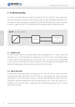
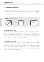
In  case  of  a  mains  voltage  failure  the  DC  UPS  UPSI-2403  supplies  the  connected  
consumer  load  with  DC  voltage  from  the  internal  battery  pack.  Via  LED  display  the 
status  is  visualised.  Via  USB  interface  signals  can  be  transfered  to  a  connected  PC  and  
operational parameters can be set.

3.1  Mains operation mode

In mains mode a voltage source at the input line supplies 24 V DC. This voltage minus 
app.  0.5  V DC  is  provided  directly  at  the  consumer  load  (e. g.  PC).  The  internal  battery 
pack  is  charged  by  the  UPSI-2403.  The  LED  is  green  and  the  USB  interface  signalises 
“Power  ok“.  App.  every  10  minutes  a  battery  test  is  performed.  In  case  of  a  defective  
battery pack or a cable brake, the LED flashes red/green.

3.2  Battery operation mode

If  the  supply  voltage  drops  below  the  switch-over  threshold  at  the  input  of  the  
DC  UPS,  the  UPSI-2403  takes  over  the  supply  of  the  connected  consumer  loads. 
The  LED  is  orange  and  the  USB  interface  signalises  “Power  Fail“.  When  the  capa-
citance  of  the  internal  battery  pack  decreases  the  UPS  management  software  
„UPSI  |  Control  Center“  displays  this  information.  When  battery  voltage  dropping     
under 21 V the LED flashes red/orange. 

Source: 


e. g. AC/DC power supply

AC

DC

DC UPS

UPSI-2403

Consumer 

load (PC)

USB Interface

Содержание UPSI-2403

Страница 1: ...Benutzerhandbuch User s Manual UPSI 2403 Deutsch English UPSI 2403 24 V 6 A...

Страница 2: ...Benutzerhandbuch UPSI 2403 2 Deutsch UPSI 2403 DC USV System...

Страница 3: ...Lieferumfang 5 1 2 Optional erh ltliches Zubeh r 5 2 Technische Daten 6 3 Funktionsprinzip 8 3 1 Netz Betrieb 8 3 2 Batterie Betrieb 8 4 LED Anzeige 9 5 Montage und Inbetriebnahme 10 5 1 DC Stecker 11...

Страница 4: ...d Lifetime Anzeige Abschaltung auch bequem ber Timerfunktion m glich Shutdown Unterdr ckung w hrend der Startphase berlast und Kurzschluss Schutz am Ausgang Automatischer Neustart durch Reboot Funktio...

Страница 5: ...nschluss Leitungen m ssen entsprechend dem Eingangsstrom der UPSI 2403 6 7 A dimensioniert und abgesichert werden Der empfohlene Querschnitt f r die Anschluss Leitungen ist 1 5 mm2 Bei Verpolung kann...

Страница 6: ...arben LED f r Power ok gr n Power Fail orange Battery low rot orange blinkend und Batterie defekt rot gr n blinkend Kurzschluss am Ausgang berlast rot Batterie berwachung Batterietest erfolgt im Norma...

Страница 7: ...a USV Software UPSI Control Center Lastsensor Via USV Software UPSI Control Center einstellbar Timerfunktion Via USV Software UPSI Control Center einstellbar in 2 Minutenschritten von 2 20 Min Zeichnu...

Страница 8: ...wird von der UPSI 2403 geladen Die LED leuchtet gr n und ber die USB Schnittstelle wird Power ok signalisiert Etwa alle 10 Minuten wird ein Batterietest durchgef hrt Bei defektem Batteriepack oder Lei...

Страница 9: ...Battery fail Batterie defekt Die LED blinkt rot gr n wenn der interne Batteriepack tief entladen oder defekt ist die Batteriezuleitung oder Sicherung defekt ist Kurzschluss am Ausgang Kurzschluss bzw...

Страница 10: ...t werden Der empfohlene Querschnitt f r die Anschluss Leitungen ist 1 5 mm2 Vor dem Einschalten ist die ordnungsgem e Verkabelung sicherzustellen Beide Batterie Sicherungen 10 A Mini Fuse m ssen geste...

Страница 11: ...te das Setzen der Parameter und m gliche Firmware Updates PIN 1 USB 2 USB D 3 USB D 4 USB 5 3 Befehlss tze Das Auslesen von Sensorwerten und das Setzen von Parametern ist ebenfalls ber Befehlss tze m...

Страница 12: ...Batteriezuleitung oder Sicherung defekt ist Weitere Anzeige Schemen siehe Seite 9 Die UPSI 2403 schaltet in Verbindung mit UPSI Control Center nicht ab Im Men Shutdown ist das H ckchen bei Herunterfah...

Страница 13: ...Benutzerhandbuch UPSI 2403 13 Deutsch Notizen...

Страница 14: ...14 English User s Manual UPSI 2403 UPSI 2403 DC UPS System...

Страница 15: ...Delivery 17 1 2 Optional Accessories 17 2 Technical Data 18 3 Functional Description 20 3 1 Mains operation mode 20 3 2 Battery operation mode 20 4 LED Display 21 5 Installation and Start up 22 5 1 D...

Страница 16: ...time display Comfortable switch off via timer function also possible Shutdown suppression during start up Output with overload and short circuit protections Battery charger protected against overtempe...

Страница 17: ...current of the UPSI 2403 6 7 A and an according additional protection must be provided and fused The recommended cross section for the connector cables is 1 5 mm2 A polarity reversal can damage the UP...

Страница 18: ...ct specific data LED display 3 colour LED for Power ok green Power Fail orange Battery low red orange flashing and Battery defect red green flashing short circuit at output overload red Battery monito...

Страница 19: ...Via UPS Software UPSI Control Center Load sensor Adjustable via UPS software UPSI Control Center Timer function Adjustable via UPS software UPSI Control Center in 2 minutes step from 2 20 min Drawing...

Страница 20: ...harged by the UPSI 2403 The LED is green and the USB interface signalises Power ok App every 10 minutes a battery test is performed In case of a defective battery pack or a cable brake the LED flashes...

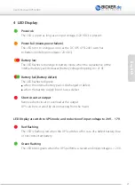
Страница 21: ...pping to 21 V Battery fail Battery defect The LED flashes red green when the internal battery pack is discharged or defect when the battery supply line or fuse is defect Short circuit at output Remove...

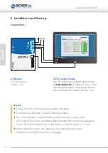
Страница 22: ...st be provided and fused The recommended cross section for the connector cables is 1 5 mm2 Before switching on the unit make sure all connections are correct Both fuses 10 A Mini Fuse must be engaged...

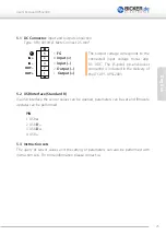
Страница 23: ...meters can be set and firmware updates can be performed PIN 1 USB 2 USB D 3 USB D 4 USB 5 3 Instruction sets The query of sensor values and the setting of parameters can also be performed with instruc...

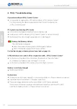
Страница 24: ...discharged or defect when the battery supply line or fuse is defect For further display schemes please have look at page 33 UPSI 2403 does not switch off in conjunction with UPSI Control Center In the...

Страница 25: ...25 English User s Manual UPSI 2403 Notes...

Страница 26: ...ma Microsoft Corp Subject to errors and technical modifications Windows is a registered trademark of Microsoft Corporation Stand Issued 22 05 2015 Bicker Elektronik GmbH Ludwig Auer Stra e 23 86609 Do...

Отзывы: