background image

Installation

 & User

 Manual

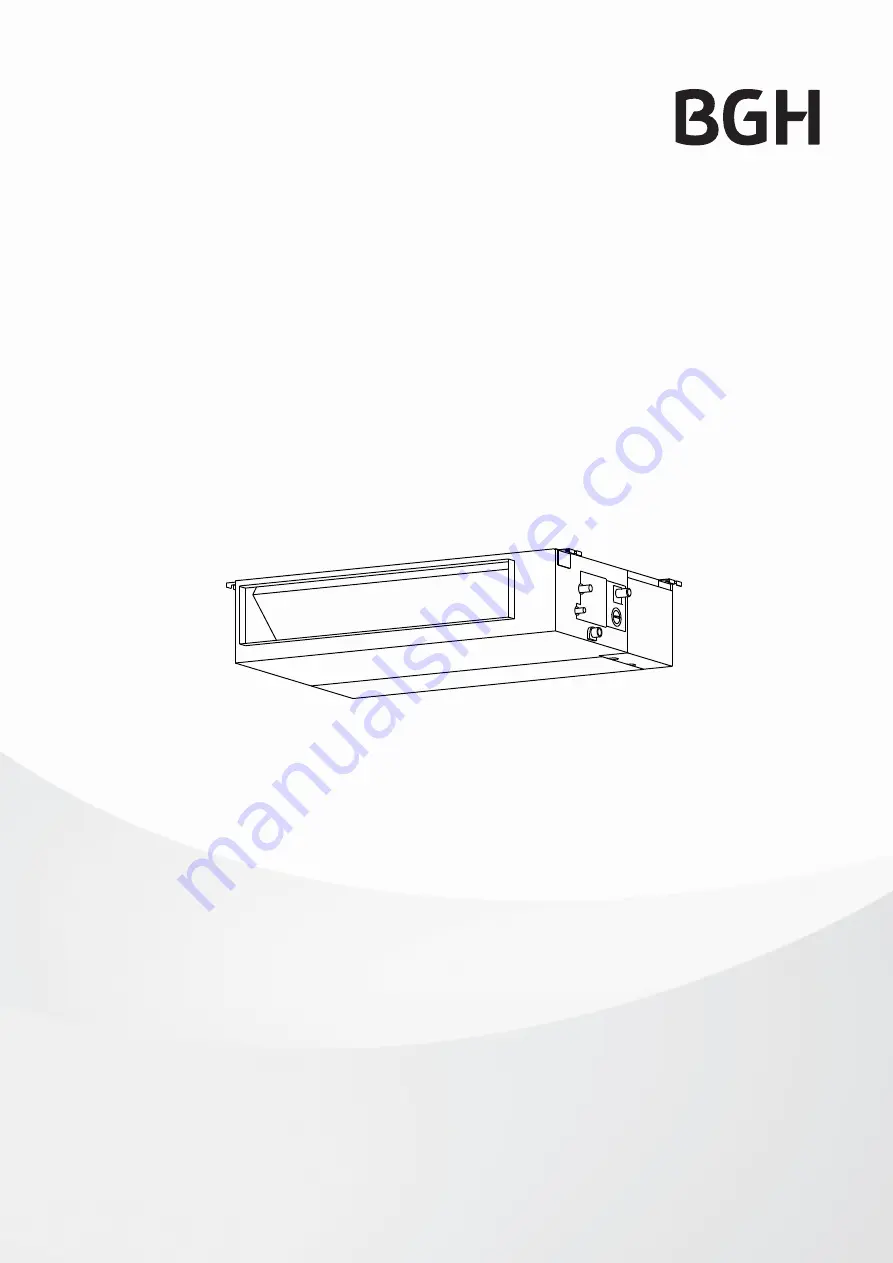
Middle Static Pressure Duct Type


Air Conditioner

Important note:

Read this manual carefully before installing or operating your new air conditioning unit. Make sure 
to save this manual for future reference.

Modelos:

BSBSM24CMO, BSBSM36CTO, BSBSM60CTO, BSBSM72CTO

Содержание BSBSM24CMO

Страница 1: ...ressure Duct Type Air Conditioner Important note Read this manual carefully before installing or operating your new air conditioning unit Make sure to save this manual for future reference Modelos BSB...

Страница 2: ......

Страница 3: ...tdoor Unit Installation 13 a Outdoor Unit Installation Instructions 13 b Outdoor Unit Types and Specifications 14 c Notes on Drilling Hole in Wall 15 Drainpipe Installation 16 Table of Contents Instal...

Страница 4: ...n 18 B Refrigerant Piping Connection Instructions 20 Wiring 23 a Outdoor Unit Wiring 23 b Indoor Unit Wiring 24 c Power Specifications 26 Air Evacuation 28 a Evacuation Instructions 28 b Note on Addin...

Страница 5: ...12 7 Packed with the indoor unit used for multi type models only NOTE Pipe size may differ from appliance to appliance To meet different pipe size requirements sometimes the pipe connections need a t...

Страница 6: ...ffect your unit and locate it accordingly Failure to do so could cause the equipment to fail After installation ensure there are no refrigerant leaks and that the unit is operating properly Refrigeran...

Страница 7: ...MC MC 6 7 Install the indoor unit Page 8 INSTALLATION ORDER Install the outdoor unit Page 13 Install the drainpipe Page 15 Evacuate the refrigeration system Page 28 Connect the wires Page 23 Connect...

Страница 8: ...n a location that meets the following requirements Enough room for installation and maintenance Enough room for the connecting pipe and drainpipe The ceiling is horizontal and its structure can sustai...

Страница 9: ...e sure to mark the paces where you will drill ceiling hook holes Maintenance space Installation place Left side Right side Strong and durable ceiling Indoor unit 4in 10cm 11 8in 30cm 0 8in 2cm 0 8in 2...

Страница 10: ...8 8 1101 43 3 508 20 598 23 5 598 23 5 697 27 4 9K 12K 200 7 9 506 19 9 700 27 6 152 6 537 21 1 450 17 7 186 7 3 741 29 2 599 23 6 360 14 2 Indoor Unit Installation Fig 4 6 Fig 4 7 Original concrete b...

Страница 11: ...m Fig 4 9 Screw nut Washer Hanging screw bolt Overhang part Shockproof cushion NOTE Confirm the minimum drain tilt is 1 100 or more CAUTION The unit body must be completely aligned with the hole Ensur...

Страница 12: ...have purchased may be slightly different in design though similar in shape Step 5 Fresh air duct installation Dimension Duct joint for fresh air 125mm 4 92 160mm 6 3 MODLE 18 60 Step 6 Motor and drai...

Страница 13: ...door unit may not exceed the maximum allowable pipe length If possible DO NOT install the unit where it is exposed to direct sunlight If possible make sure the unit is located far away from your neigh...

Страница 14: ...845x700x320 33 27x27 5x12 6 560 22 335 13 2 900x860x315 35 4x33 85x12 4 590 23 2 333 13 1 945x810x395 37 2x31 9x15 55 640 25 2 405 15 95 990x965x345 38 98x38x13 58 624 24 58 366 14 4 946x810x420 37 24...

Страница 15: ...protects the edges of the hole and will help seal it when you finish the installation process Outdoor Unit Installation Fig 5 11 L H 300 cm 118 or more A 60 cm 23 6 or more 150 cm 59 or more 25 cm 9 8...

Страница 16: ...ondensation which could lead to water damage If the drainpipe is bent or installed incorrectly water may leak and cause a water level switch malfunction In HEAT mode the outdoor unit will discharge wa...

Страница 17: ...roper water drainage See Fig 6 5 Place the protective wall cuff in the hole This protects the edges of the hole and will help seal it once you finish installation Wall Indoor Outdoor 12mm 0 5 inch Fig...

Страница 18: ...nsure there is no refrigerant leakage after completing the installation work Notes On Pipe Length and Elevation Ensure that the length of the refrigerant pipe the number of bends and the drop height b...

Страница 19: ...the rising gas piping can prevent this CAUTION The indoor unit is installed higher than the outdoor unit If the outdoor unit is installed higher than the indoor unit It is recommended that vertical su...

Страница 20: ...m Liquid side 12 7 0 5 15 9 0 626 15 9 0 626 6 35 0 25 9 5 0 375 9 5 0 375 18K 24K 30K Size of joint pipes for 410A indoor unit Table 7 3 CE FQZHN 01C CE FQZHN 01C CE FQZHN 01C Available branching pip...

Страница 21: ...f the pipe for cracks and even flaring Step 4 Connect pipes Connect the copper pipes to the indoor unit first then connect it to the outdoor unit You should first connect the low pressure pipe then th...

Страница 22: ...pper pipes to the indoor unit wrap the power cable signal cable and the piping together with binding tape NOTE DO NOT intertwine signal cable with other wires While bundling these items together do no...

Страница 23: ...made through a switch that disconnects all poles with contact gap of at least 3mm 0 118 DO NOT modify the length of the power cord or use an extension cord CAUTION Connect the outdoor wires before co...

Страница 24: ...parts 6 Reinstall the cover of the electric control box Indoor Unit Wiring 1 Prepare the cable for connection a Using wire strippers strip the rubber jacket from both ends of the signal cable to reve...

Страница 25: ...h the designed airflow rate Make sure the unit is in FAN ONLY mode Press and set the airflow adjustment button on the remote control to change the airflow rate from H or L 4 Set the parameters for aut...

Страница 26: ...PHASE 1 Phase 1 Phase 1 Phase 3 Phase 3 Phase VOLT 208 240V 208 240V 208 240V 208 240V 208 240V CIRCUIT BREAKER FUSE A 25 20 32 25 50 40 70 55 70 60 MODEL Btu h 36K 37K 72K 36K 37K 72K POWER PHASE 3 P...

Страница 27: ...WER indoor PHASE 1 Phase 1 Phase 1 Phase 1 Phase VOLT 208 240V 208 240V 208 240V 208 240V CIRCUIT BREAKER FUSE A 15 10 15 10 15 10 15 10 POWER outdoor PHASE 3 Phase 3 Phase 3 Phase 3 Phase VOLT 380 42...

Страница 28: ...old gauge Keep the High Pressure side closed 4 Turn on the vacuum pump to evacuate the system 5 Run the vacuum for at least 15 minutes or until the Compound Meter reads 76cmHG 1x10⁵Pa 6 Close the mani...

Страница 29: ...depending on pipe lengths The standard pipe length varies according to local regulations For example in North America the standard pipe length is 7 5m 25 In other areas the standard pipe length is 5m...

Страница 30: ...correctly d Ensure the indicators on the remote control and the display panel on the indoor unit work properly e Ensure the manual buttons on the indoor unit works properly f Check to see that the dra...

Страница 31: ...QC5 Outdoor Unit MOT4V 36CN1 QC5 shall be connected only to a supply of the system impedance Zsys 0 024 or less Before connecting the product to public power network please consult your local power s...

Страница 32: ...Indoor Unit Parts and Major Functions 05 Manual Operations 07 Table of Contents Owner s Manual SAFETY FIRST Safety Precautions 04 1 2 3...

Страница 33: ...a Unit Maintenance 08 b How to Clean the Air Filter 08 c Repairing Refrigerant Leaks 09 d Preparation for Periods of Non use 09 Troubleshooting 10 a Common Problems 10 b Troubleshooting Tips 11 Europe...

Страница 34: ...ay result in death The appliance must be installed in accordance with national regulations Failure to observe a caution may result in injury or equipment damage WARNING CAUTION DO NOT place items that...

Страница 35: ...efficient Indoor Unit Parts And Major Functions Air outlet Air inlet Air filter on some models Drain hose Electric control cabinet Refrigerant connecting pipe COOL Mode HEAT mode DRY mode Indoor Temp...

Страница 36: ...in the room DO NOT place objects near the air inlet and outlet of the unit Set a timer and use the built in SLEEP ECONOMY mode if applicable If you don t plan to use the unit for a long time remove th...

Страница 37: ...r AUTO FORCED COOL OFF FORCED COOL mode In FORCED COOL mode the Operation light flashes The system will then turn to AUTO after it has cooled with a high wind speed for 30 minutes The remote control w...

Страница 38: ...em and disconnect the power supply before cleaning or maintenance DO NOT use chemicals or chemically treated cloths to clean the unit DO NOT use benzene paint thinner polishing powder or other solvent...

Страница 39: ...play EC and the LED indicator light will flash Preparation For Periods Of Non Use Maintenance after Extended Non Use 1 Remove any obstacles blocking the vents of both the indoor and outdoor units 2 Cl...

Страница 40: ...its setting to prevent frost from forming on the unit Once the temperature increases the unit will start operating again The set temperature has been reached at which point the unit turns off the comp...

Страница 41: ...outdoor unit is dirty Clean the affected heat exchanger The air filter is dirty Remove the filter and clean it according to instructions The air inlet or outlet of either unit is blocked Turn the unit...

Страница 42: ...y Memory error 1 Off E0 2 3 Indoor fan speed malfunction 4 Off E3 4 Indoor room temperature sensor error 5 Off E4 5 Evaporator coil temperature sensor error 6 Off E5 6 Refrigerant leak detection syste...

Страница 43: ...al waste When disposing of this appliance you have the following options Dispose of the appliance at designated municipal electronic waste collection facility When buying a new appliance the retailer...

Страница 44: ...Page 16...

Страница 45: ...Page 17...

Страница 46: ...Page 18...

Отзывы: