


INSTALLATION MANUAL
ENGLISH
Thank you for buying this product. Our company is sure that you will be more
than satisfied with the product’s performance.
Carefully read the
“WARNINGS”
pamphlet and the
“INSTRUCTION
BOOKLET”
which are supplied together with this product, since they provide
important information regarding the safety, installation, use and maintenance
of the product. This product complies with recognised technical standards
and safety regulations. We declare that this product is in conformity with the
following European Directives: 89/336/EEC, 73/23/EEC and subsequent
amendments.
1) GENERAL SAFETY
WARNING! An incorrect installation or improper use of the product
can cause damage to persons, animals or things.
• The “
Warnings
” leaflet and “
Instruction booklet
” supplied with this
product should be read carefully as they provide important information
about safety, installation, use and maintenance.
• Scrap packing materials (plastic, cardboard, polystyrene etc) according
to the provisions set out by current standards. Keep nylon or polystyrene
bags out of children’s reach.
• Keep the instructions together with the technical brochure for future
reference.
• This product was exclusively designed and manufactured for the use
specified in the present documentation. Any other use not specified in
this documentation could damage the product and be dangerous.
• The Company declines all responsibility for any consequences result-
ing from improper use of the product, or use which is different from that
expected and specified in the present documentation.
• Do not install the product in explosive atmosphere.
• The construction components of this product must comply with the following
European Directives: 89/336/CEE, 73/23/EEC, 98/37/EEC and subse-
quent amendments. As for all non-EEC countries, the above-mentioned
standards as well as the current national standards should be respected
in order to achieve a good safety level.
• The Company declines all responsibility for any consequences resulting
from failure to observe Good Technical Practice when constructing clos-
ing structures (door, gates etc.), as well as from any deformation which
might occur during use.
• The installation must comply with the provisions set out by the following
European Directives: 89/336/CEE, 73/23/EEC, 98/37/EEC and subsequent
amendments.
• Disconnect the electrical power supply before carrying out any work on
the installation. Also disconnect any buffer batteries, if fitted.
• Fit an omnipolar or magnetothermal switch on the mains power supply,
having a contact opening distance equal to or greater than 3,5 mm.
• Check that a differential switch with a 0.03A threshold is fitted just before
the power supply mains.
• Check that earthing is carried out correctly: connect all metal parts for
closure (doors, gates etc.) and all system components provided with an
earth terminal.
• Fit all the safety devices (photocells, electric edges etc.) which are needed
to protect the area from any danger caused by squashing, conveying and
shearing.
• Position at least one luminous signal indication device (blinker) where it
can be easily seen, and fix a Warning sign to the structure.
• The Company declines all responsibility with respect to the automation safety
and correct operation when other manufacturers’ components are used.
• Only use original parts for any maintenance or repair operation.
• Do not modify the automation components, unless explicitly authorised
by the company.
• Instruct the product user about the control systems provided and the
manual opening operation in case of emergency.
• Do not allow persons or children to remain in the automation operation
area.
• Keep radio control or other control devices out of children’s reach, in
order to avoid unintentional automation activation.
• The user must avoid any attempt to carry out work or repair on the automa-
tion system, and always request the assistance of qualified personnel.
• Anything which is not expressly provided for in the present instructions,
is not allowed.
• Installation must be carried out using the safety devices and controls
prescribed by the EN 12978 Standard.
2) GENERAL OUTLINE
This controller has been designed to motorize counter-balanced overhead
doors.
The compactness and versatility of the installation allow the motor drive to be
fitted to almost any model of overhead door where it can be installed both in the
centre and at the side. It is particularly recommended for residential use.
The irreversible gearmotor keeps the door locked in the closing position
without electric lock.
In the case where the mains power supply is off, release is activated from
the inside by means of an appropriate knob. The release device if provided
with microswitches, which stop the motor both on opening and on closing,
and with a timed courtesy light.
The following versions are available:
PHEBE/PHEBE IP44
Model with built-in control unit (
HYDRA
) controlling one or two controllers.
PHEBE-SQ/PHEBE-SQ IP-44
Model without control unit indispensable for automations with two controllers
PHEBE, the first of which is PHEBE and the second is PHEBE-SQ. They
can be also used in case of wall-mounted control unit.
PHEBE C
Version for articulated-panel overhead doors with an incorporated control
unit (HYDRA) suitable for controlling one or two operators.
PHEBE C-SQ
Version for articulated-panel overhead doors without a control unit, indis-
pensable for automation systems with two PHEBE actuators, the first being
PHEBE C and the second PHEBE C-SQ. These can also be used when the
control unit is to be wall-mounted.
PHEBEKIT
Model available in kit used for overhead doors with a door panel of up to
7m
2
. It is equipped with a built-in control unit Mod. HYDRA.
CAUTION -
The controllers without pre-assembled control unit, must be
controlled by a control unit featuring electronic torque adjustment (series
HYDRA).
3) TECHNICAL SPECIFICATIONS
Power supply: ...............................................................230V±10%50Hz (*)
Motor: ............................................................................24V
1500 min
-1
Motor Power:PHEBE/PHEBE-SQ IP44/PHEBE IP44: ......................... 40W
PHEBE C/PHEBE-C SQ IP44/PHEBE C IP44: ........ 45W
Insulation class: ........................................................................................ F
Lubrication: .................................................................... Permanent grease
Reduction ratio: .................................................................................. 1/812
Output shaft revolutions: ......................................................1.8 min-1 MAX
Output shaft: ............................................... Shaft with through wire 20X20
Opening time: ............................................................................... 17 - 20 s
Torque supplied: PHEBE/PHEBE-SQ IP44/PHEBE IP44: ..............300 Nm
PHEBE C/PHEBE-C SQ IP44/PHEBE C IP44: ...330 Nm
Operation limits: ...............................1 Motor X 7sqm / 2 Motors X 10sqm
Impact reaction: .................................................... Integrated torque limiter
on HYDRA control panel
Limit switches: .................................. Electric, incorporated and adjustable
Manual manoeuvre: ............................................................... Knob release
Number of manoeuvres in 24 hours: ...................................................... 40
Courtesy light: ...................................................................24V
~
Max 25W
Working temperature: .............................................................. -15 +60° C
Degree of protection
PHEBE/PHEBE C: .............................................................................. IP30
PHEBE-SQ IP44/PHEBE IP44: ...........IPX4 (Electrical components:IP44)
Operator weight: .................................................................................10 kg
Dimensions: .................................................................................. See fig.1
(*) Special voltages on request
4) INSTALLATION OF THE AUTOMATION
Preliminary checks
Check:
• that the structure of the door is sturdy and strong enough
• that the door is properly balanced
• that the door can be slid manually and runs smoothly along the whole of
its stroke
If the door being installed is not new, check whether its components are worn.
Repair or replace any worn or damaged parts.
Automation reliability and safety are directly influenced by the condition of
the overhead door structure.
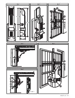
5) INSTALLATION
5.1) Required accessories:
Telescopic arm kit - Pair of driving pipes - Fixing base
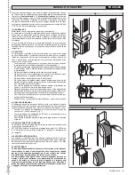
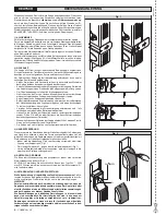
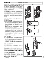
5.2) Actuator fitting (Fig.2)
• Secure the actuator to the fixing base by means of the four screws (A)
supplied, finding the most favourable position for installation (see dimen-
12 -
PHEBE Ver. 03
D811328_03
D811328_03
D811328_03
D811328_03
Содержание PHEBE
Страница 2: ...2 PHEBE Ver 03 D811328_03 D811328_03 D811328_03 D811328_03...
Страница 32: ......