


DATI TECNICI
DATI ELETTRICI
Alimentazione
220-230V 50/60Hz
Potenza max. assorbita dalla rete 200 W
Fusibili
vedi Fig. L-S
Alimentazione accessori
24V~ (180mA max)
24Vsafe (180mA max)
Collegamento lampeggiante
24V~ max 25W
Luce cortesia
Lampadina a led di cortesia mod. BFT 24V
2W
Temperatura di funzionamento
-20°C / +60°C
Apertura pedonale
20% della corsa totale
Attivabile via filo su ingresso IC2 (Fig. L)
oppure
attivabile via radio con memorizzazione
MEM2 (Fig.N)
DATI MECCANICI
Forza trazione e spinta
650 N
Anta max
10m2
Corsa utile
BINARIO L.=2900 corsa utile=2290 mm
BINARIO L.=3500 corsa utile=2890 mm
Velocità massima
BINARIO a cinghia= 240 mm/s
BINARIO a catena= 210 mm/s
Manovre in 24 ore @ MAX+60°C 50
Manovre in 1 ora @ MAX+50°C
10
Installazione tipica sezionale mq
5,5 a 20°C
130 manovre consecutive
Reazione all’urto
Limitatore di coppia integrato su quadro
comando
Finecorsa
Elettronico ad ENCODER
Lubrificazione
Grasso permanente
Grado di protezione
IP20
Peso testamotore
5 kg
Rumorosità
<70dB(A)
Dimensioni
Vedi fig.B
DATI RICEVITORE INCORPORATO
Radioricevente Rolling-Code in-
corporata
Frequenza 433.92 MHz
Codifica
Algoritmo Rolling-Code
N° combinazioni
4 miliardi
N° max radiocomandi memorizzabili 63
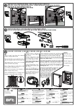
INSTALLAZIONE ATTUATORE Fig.A
Predisporre l’arrivo dei collegamenti degli accessori, dei dispositivi di sicurezza
e di comando al gruppo motore tenendo nettamente separati i collegamenti a
tensione di rete dai collegamenti in bassissima tensione di sicurezza (24V). Pro-
cedere al loro collegamento come indicato nello schema elettrico.
I cavi di connessione accessori devono essere protetti da canaletta.
Verifiche preliminari:
• Controllare il bilanciamento della porta.
• Controllare lo scorrimento della porta per tutta la corsa.
• Se la porta non è di nuova installazione, controllare lo stato di usura di tutti i
componenti.
• Sistemare o sostituire le parti difettose o usurate.
• L’affidabilità e la sicurezza dell’automazione è direttamente influenzata dallo
stato della struttura della porta.
• Prima di installare il motore, togliere eventuali funi o catene superflue e disa-
bilitare qualsiasi apparecchiatura non necessaria.
ITALIANO
ENGLISH
TECHNICAL SPECIFICATIONS
ELECTRICAL DATA
Power supply
220-230V 50/60Hz
Max. power absorbed from mains 200 W
Fuses
see figure L-S
Supply to accessories
24V~ (180mA max)
24Vsafe (180mA max)
Blinker connection
24V~ max 25W
Courtesy light
BFT model courtesy LED lamp 24V
2W
Operating temperature
-20°C / +60°C
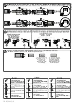
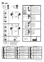
Pedestrian opening
20% of the total travel
Can be activated via wire on input IC2 (Fig. L)
or
via radio with memorization MEM2 (Fig.N)
MECHANICAL DATA
Pulling and pushing force
650 N
Leaf max.
10m2
Working stroke
TRACK L.=2900 working stroke= 2290 mm
TRACK L.=3500 working stroke= 2890 mm
Maximum speed
Belt track = 240 mm/s
Chain track = 210 mm/s
Manoeuvres in 24 hours@ MAX+60°C 50
Manoeuvres in 1 hour@ MAX+50°C
10
Typical installation of sectional
doors sqm 5,5 at 20°C
130 consecutive manoeuvres
Impact reaction
integrated torque limiter on control panel
Limit switch
Electronic with ENCODER
Lubrication
permanent grease
Degree of protection
IP20
Motor head weight
5 kg
Noise level
<70dB(A)
Dimensions
see fig.B
INCORPORATED RECEIVER DATA
Incorporated rolling-code radio
receiver
Frequency 433.92 MHz
Coding
rolling-code algorithm
No. combinations
4 billion
Max no. radio controls to be
memorised
63
ACTUATOR INSTALLATION Fig.A
Arrange for the connections of accessories and safety and control devices to reach
the motor unit, keeping the mains voltage connections clearly separate from the
extra low safety voltage connections (24V).
Proceed to connection following the indications given in the wiring diagram.
The cables for connecting the accessories must be protected by a raceway
Preliminary checks
• Check that the door is balanced.
• Check that the door slides smoothly along its entire travel.
• If the door has not been newly installed, check the wear condition of all its
components.
• Repair or replace faulty or worn parts.
• The automation reliability and safety are directly influenced by the state of
the door structure.
• Before fitting the motor, remove any superfluous ropes or chains and disable
any unnecessary appliances.
BOTTICELLI BT A 650 -
21
D813947 00100_02