background image

11

MACHINE PREPARATION

18. FILLING THE SOLUTION TANK

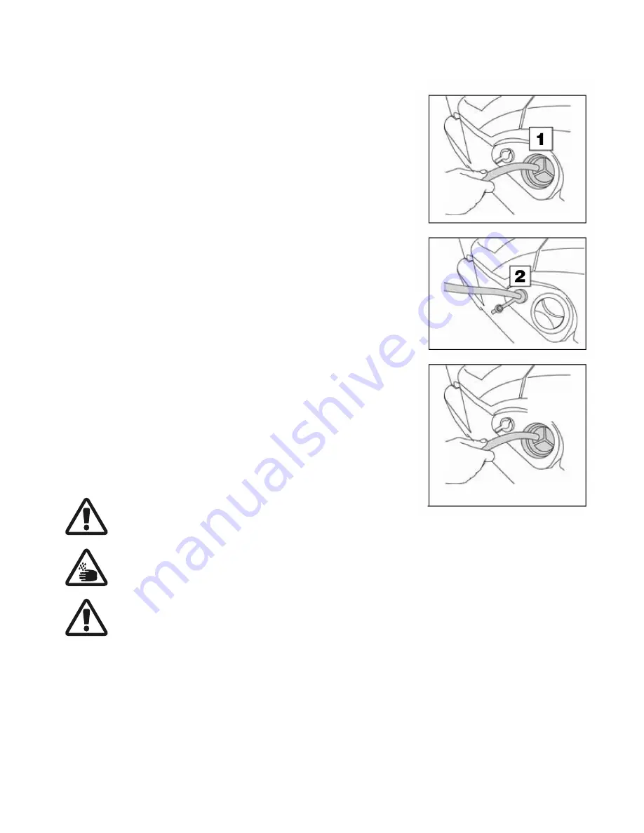
The solution tank can be filled in two different ways:

1.  Unscrew the primary filling cap and fill using a hose.

2.  Use the secondary filling port that is equipped with a rubber cap to hold the 

hose in place during filling.  This port is particularly useful when filling with a 

Betco FastdDraw

®

 chemical dispenser.

Fill with clean water at a temperature not exceeding 120° F.  The amount of water 

present in the tank can be seen through the visual sight level gauge near the 

front left of the seat.
The solution tank has a maximum capacity of 29 gallons.  Add Betco liquid 

detergent to the tank in the concentration and manner indicated on the label.  

The formation of excessive foam will damage the vacuum motor, so use only the 

minimum amount of detergent that is necessary.

WARNING: Always use detergents whose manufacturer's label 

indicates their suitability for scrubbing machines. Do not use acid 

or alkaline products or solvents without this indication.  

ATTENTION: Protective gloves should always be worn before han-

dling detergents or acidic or alkaline solutions to avoid serious 

injury to hands.  

ATTENTION: always use low foam detergent. To avoid the produc-

tion of foam, before starting to clean, put a minimum quantity of 

antifoam liquid into the recovery tank. Do not use pure acids.

Содержание E29926-00

Страница 1: ... GO BETCO Fax 800 445 5056 Technical Service 877 856 5954 www betco com Operator Manual E29926 00 26 w Wet Batteries E29927 00 26 w AGM Batteries E29931 00 32 w Wet Batteries E29932 00 32 w AGM Batteries 26 and 32 Automatic Rider Scrubbers STEALTH DRS RIDER SERIES ...

Страница 2: ...S 4 GENERAL SAFETY REGULATIONS 5 MACHINE PREPARATION 6 14 OPERATION 15 AT END OF WORK 16 DAILY MAINTENANCE 17 19 WEEKLY MAINTENANCE 20 IRREGULAR MAINTENANCE 21 TROUBLESHOOTING 22 23 CHOOSING AND USING THE BRUSHES 23 STEALTH BRUSH OPTIONS AND COMMON PARTS 23 WARRANTY 24 ...

Страница 3: ...king order We therefore suggest you read this instruction booklet carefully and re read it whenever difficulties arise while using the machine Please contact our techni cal service department or your dealer if you have any questions about the machine RECEIVING THE MACHINE SYMBOLS USED ON THE MACHINE Main Key Switch Symbol Used on the control panel to indicate the key switch position for ON or OFF ...

Страница 4: ... 24 0 6 2 Drive Type Automatic Vacuum motor V HP 24 0 5 Vacuum motor suction inches of water mbar 75 6 188 Solution tank capacity Gal l 29 110 Recovery tank capacity Gal l 33 125 Weight of machine excluding batteries lb Kg 490 225 Batteries V Ah 6 235 4 or 6 200 4 Charger V A 24 25 Machine dimensions Length Height Width in x in x in 59 x 52 x 28 59 x 52 x 34 Noise level dBA 58 TECHNICAL DESCRIPTIO...

Страница 5: ... not hit against shelving or scaffolding The operator must always be equipped with the appropriate safety device gloves shoes helmet glasses etc Do not use the machine on surfaces with an inclination greater than the one shown on the serial plate The machine is designed to wash and dry floors simultaneously Signal the presence of wet floors with suitable signs If the machine does not work properly...

Страница 6: ... UNPACK THE MACHINE Begin by removing the outer corrugated box The machine is fixed to the pallet with wedges to block the wheels in place Remove the wedges from the pallet Use a ramp to get the machine off the pallet pushing it backwards Do not install the rear squeegee assembly before unloading the machine Avoid violently jolting the brush base when removing the machine from a pallet Keep the pa...

Страница 7: ...ENTS The instrument panel components are identified as follows 1 Main Key Switch 2 Battery Discharge Indicator and Hour Meter 3 Operation Switch I DRIVE Device Choose the desired operating program with the I DRIVE device A Transfer Movement of the machine without working B Drying Use the squeegee only C Scrubbing and Drying Use both the scrub brushes and the squeegee D Scrubbing Only Use the scrub...

Страница 8: ...oard are identified as follows 10 Lock Down Head Pressure Lever 11 Solution Level Sight Gauge 9 SIDE MACHINE COMPONENTS The side components of the machine are identified as follows 12 Primary Solution Filling Port 13 Solution Hose Filling Port 14 Solution Tank Discharge Hose 10 MACHINE REAR COMPONENTS The rear components of the machine are identified as follows 15 Recovery Tank Discharge Hose MACH...

Страница 9: ... Make sure the recovery tank is empty Move the machine to the battery charger Make sure that the key switch is in the OFF position Engage the parking brake Grip the handle under the seat to open the recovery tank Lift the recovery tank until it hooks to the end of the safety clamp Disconnect the Anderson plug connection between the batteries and the machine Connect the Anderson plug from the batte...

Страница 10: ...usted by how far the drive pedal is pushed down The machine is programmed to drive slower in reverse than it does in for ward However the speed of travel in reverse is also regulated by how far the drive pedal is pushed down 16 RECOVERY TANK The recovery tank must be completely emptied each time the solution tank is filled Make sure the recovery tank is empty if not be sure to drain it completely ...

Страница 11: ...s a maximum capacity of 29 gallons Add Betco liquid detergent to the tank in the concentration and manner indicated on the label The formation of excessive foam will damage the vacuum motor so use only the minimum amount of detergent that is necessary WARNING Always use detergents whose manufacturer s label indicates their suitability for scrubbing machines Do not use acid or alkaline products or ...

Страница 12: ... pins are in place tighten the finger wheels 1 and 2 to lock the squeegee in place Connect the vacuum hose to the squeegee shoe 3 20 SQUEEGEE ANGLE During operation the squeegee assembly should be tilted slightly backward in a uniform manner across the entire length If it is necessary to increase the incline of the squeegee in the center por tion the adjuster screw 1 will need to be rotated clockw...

Страница 13: ... is locked into place by the coupling spring The image to the right shows the rotation direction to lock in the right side brush The rotation is opposite for the left side brush If using brushes on this machine it is advised to rotate the left and right side brushes every day However if the brushes have not been rotated for a lengthy period of time and have deformed bristles it is advised to reass...

Страница 14: ...machine has an electronic braking system To brake in normal condi tions simply remove your foot from the accelerator pedal and the machine will stop In extreme cases it may be necessary to activate the manual brake pedal 13 by pushing it downward Be sure to release your foot from the accelerator pedal when pushing the manual brake To engage the parking brake press down the manual brake pedal 13 an...

Страница 15: ... Drive control 11 The brush and squeegee assemblies will raise and discontinue working when the machine is selected to travel in reverse During the first 20 feet of travel check that there is sufficient solution and that the squeegee is drying the floor The machine will continue to scrub and dry until it runs out of solution or the batteries are completely discharged A flashing red warning light a...

Страница 16: ...yourself from contact with hazardous chemicals 7 Remove the vacuum hose 4 from the squeegee shoe 8 Remove the squeegee assembly 5 from the support arm by unscrewing the finger wheels 6 9 Clean the squeegee blades and squeegee shoe with clean water 10 Re install the squeegee assembly on the support arm first insert the left pin into the slot and then the right Be sure to keep the tension spring and...

Страница 17: ... the squeegee assembly 4 Close the cap on the drain hose and return it to the holding clamps 5 Close the recovery tank lid by lifting it slightly to disengage the support prop 3 and lowering it until it is closed 31 CLEAN THE VACUUM MOTOR FILTER 1 Open the recovery tank lid 2 and insert the support prop into the hook 3 on the underside of the lid 2 Remove the vacuum filter housing 4 by rotating it...

Страница 18: ...queegee assembly in place 7 Attach the vacuum hose 1 to the squeegee shoe WARNING Always wear gloves when doing this operation to pro tect yourself from contact with hazardous chemicals WARNING Before performing any maintenance remove the keys from the control panel and disconnect the battery connection to the machine 33 CLEAN THE FILTER AND SOLUTION TANK 1 Disconnect the solution drain hose 1 fro...

Страница 19: ... right side brush The rotation is opposite for the left side brush WARNING Always wear gloves when doing this operation to pro tect yourself from contact with hazardous chemicals WARNING Before performing any maintenance remove the keys from the control panel and disconnect the battery connection to the machine If using brushes on this machine it is advised to rotate the left and right side brushe...

Страница 20: ...ng this operation to pro tect yourself from contact with hazardous chemicals WARNING Before performing any maintenance remove the keys from the control panel and disconnect the battery connection to the machine 4 Remove the vacuum hose from the squeegee shoe 5 Make sure the recovery tank is empty if not drain the tank completely 6 Grip the handle under the operator seat and open the recovery tank ...

Страница 21: ...l panel 2 Remove the squeegee from the support arm by unscrewing the finger wheels 3 Turn all of the wing nuts 1 to a horizontal position 4 Remove the rear side squeegee retaining plates 2 5 Remove the rear squeegee blade 3 6 Proceed in reverse order to replace the blade 7 If replacing the squeegee blade it may be necessary to adjust the height of the squeegee assembly see section titled Adjusting...

Страница 22: ...XCESSIVE FOAM 1 Verify that low foam detergent is being used 2 Verify that the detergent is being diluted at the proper ratio 3 If necessary add a small quantity of de foaming liquid to the recovery tank 4 When the floor is not very dirty more foam will be generated In this case the detergent may need to be diluted to a lower concentration 43 INSUFFICIENT SUCTION FROM THE VACUUM MOTOR 1 Check to s...

Страница 23: ...oors or floors with very shallow joints On uneven floors or those with deep joints it is advised to use softer bristles which can flex to enter the joints more easily Remember that when the bristles are worn and too short they will become more rigid and will no longer penetrate into the deep joints PAD DRIVER The pad holder is recommended for cleaning shiny surfaces There are two types of pad hold...

Страница 24: ...ts except wear items are warranted by Betco for a period of 3 years Wear Items exempt from Warranty consideration include but may not be limited to power cords transport wheels vacuum bags belts squeegee blades pad drivers clutch plates handle grips filters screens throttle cables brushes and carbon brushes Subject to the conditions and exceptions stated in this warranty Betco warrants the Betco p...

Отзывы: