27
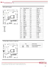
LVDS (LVDS Header)
Pin
Signal Name Pin
Signal Name
1
VCC3
21
A5P_C
2
VCC
22
A4P_C
3
VCC3
23
A5M_C
4
VCC
24
A4M_C
5
SPC0
25
GND
6
SPD0
26
GND
7
GND
27
A7P_C
8
GND
28
A6P_C
9
A1P_C
29
A7M_C
10
A0P_C
30
A6M_C
11
A1M_C
31
GND
12
A0M_C
32
GND
13
GND
33
CLK2P_C
14
GND
34
CLK1P_C
15
A3P_C
35
CLK2M_C
16
A2P_C
36
CLK1M_C
17
A3M_C
37
GND
18
A2M_C
38
GND
19
GND
39
+12V
20
GND
40
+12V
CI (Case Open Inverter Connector)
Pin
Definition
Open
Normal Operation
Close
Alert Active
Содержание BNX-M81
Страница 1: ...1 Embedded Board BNX M81 Always at the forefront of innovation User Manual...
Страница 6: ...6 Chapter 1 General Information...
Страница 9: ...9 Figure 1 1 Board Layout of BNX M81 1 3 Board Layout...
Страница 10: ...10 Chapter 2 Preparation...
Страница 14: ...14 2 5 Locations Of Jumpers and Connectors...
Страница 20: ...20 CLR_CMOS Clear CMOS Jumper Pin Definition Open Normal Operation Close Clear CMOS...
Страница 28: ...28 Chapter 3 Operation...
Страница 36: ...36 Chapter 4 BIOS Setup...


