26
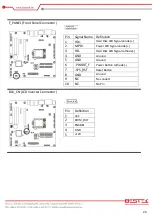
F_PANEL (Front Panel Connector)
Pin
Signal Name Definition
1
HD+
Hard Disk LED Signal anode (+)
2
MPD+
Power LED Signal anode (+)
3
HD-
Hard Disk LED Signal cathode(-)
4
GND
Ground
5
GND
Ground
6
-PWRBT_F
Power Button cathode(-)
7
-SYS_RST
Reset Button
8
GND
Ground
9
NC
No connect
10
NC
No Pin
BLK_CN (LCD Inverter Connector)
Pin
Definition
1
VCC
2
PWM_OUT
3
ENABKL
4
GND
5
+12V
Содержание BNX-M81
Страница 1: ...1 Embedded Board BNX M81 Always at the forefront of innovation User Manual...
Страница 6: ...6 Chapter 1 General Information...
Страница 9: ...9 Figure 1 1 Board Layout of BNX M81 1 3 Board Layout...
Страница 10: ...10 Chapter 2 Preparation...
Страница 14: ...14 2 5 Locations Of Jumpers and Connectors...
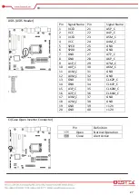
Страница 20: ...20 CLR_CMOS Clear CMOS Jumper Pin Definition Open Normal Operation Close Clear CMOS...
Страница 28: ...28 Chapter 3 Operation...
Страница 36: ...36 Chapter 4 BIOS Setup...


