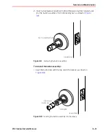
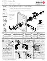
Best 7KC Series Скачать руководство пользователя страница 38

Latch tube prongs

Patas del tubo del cerrojo
Griffes du cylindre

Chassis frame

Marco del chasis
Logement du barillet

Latch tailpiece

Pieza trasera del cerrojo
Partie arrière du pêne dormant

Retractor

Retractor
Rétracteur

Install inner liner.

IInstale el revestimiento interior.
Installez la gaine intérieure.

10

Press the rose on the liner.

Presione la roseta en el 
revestimiento.
Appuyez la rosette sur la gaine.

11

Press the lever on

.

Presione la palanca hacia 
adelante.
Appuyez sur le levier.

12

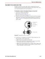
For R function locks only, insert a screwdriver into 
the figure-8 opening and turn the locking 
mechanism counterclockwise as far as it will go.

Para las cerraduras que solo tienen función R, inserte un 

destornillador en la apertura de la figura ocho y gire el mecanismo de 
bloqueo en sentido contrario al de las agujas del reloj lo más posible.
Pour les verrouillages de la 
fonction R uniquement, 
insérez un tournevis dans 
l’ouverture en forme de huit 
et tournez le mécanisme de 
verrouillage dans le sens 
inverse des aiguilles d’une 

montre.

15

Note:

 The lever points to the hinges.

Nota:

 La palanca apunta a las bisagras.

Note :

 Le levier pointe vers les charnières.

Deadlocking plunger

Émbolo del punto de bloqueo

Plongeur de verrouillage

Caution: 

Make sure the 

control key is protected.

Precaución:

 Asegúrese de que 

la llave de control esté 
protegida.

Mise en garde :

 Assurez-vous 

que la clé de contrôle est 
protégée.

Install the strike box and 
plate.

IInstale la caja del pasador y la 
placa.

Installez la boîte de la gâche et la plaque.

13

Insert the throw member 
and the control key.

Inserte el miembro de alzada 
y la llave de control.

Insérez la pièce de projection et la clé 
de contrôle.

16

Rotate the key 15° counterclockwise 
and remove the key.

Gire la llave 15° en el sentido contrario al de 
las agujas del reloj y extraiga la llave.

Tournez la clé de 15° dans le sens antihoraire et retirez 
la clé.

18

Mortise the jamb. See caution in 
step 14.

Aplique la mortaja en el montante. 
Consulte la precaución en el paso 14.
Mortaisez l’embrasure de porte. Consultez 
la mise en garde à l’étape 14.

Caution

:  The deadlocking plunger of the latch must not enter the strike plate opening. The plunger deadlocks the latchbolt to prevent forcing.  

Precaución:


El émbolo de punto de bloqueo 

del pestillo no debe ingresar en la apertura de la placa del pasador. El émbolo aplica el punto de bloqueo en el perno del pestillo para evitar que se fuerce.  

Mise en garde :


Le piston de 

verrouillage du loquet ne doit pas pénétrer dans l’ouverture de la gâche. Le piston bloque le loquet pour éviter de forcer. 

Caution

:  A gap of more than 1/8" may reduce security and/or cause improper operation of the latchbolt.


Precaución: 

Un espacio de más de 3.15 mm (1/8 pulg.) puede ser menos seguro y 

hacer que el pasador funcione incorrectamente.  

Mise en garde :


Un écart de plus de 3,18 mm (1/8 po) peut réduire la sécurité et/ou causer un mauvais fonctionnement du pêne à ressort. 

14

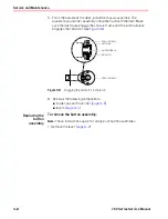
Insert chassis assembly into door, engage retractor in latch.

Inserte el conjunto del chasis en la puerta, enganche el retractor en el pestillo.
Insérez l'ensemble du barillet dans la porte, insérez le rétracteur dans le loquet.

9

15°

15°

Rotate the key 15° clockwise 
and insert core into the lever.

Gire la llave 15° en el sentido de 
las agujas del reloj e inserte el 

núcleo en la palanca.
Tournez la clé de 15° dans le sens horaire et 
insérez le noyau dans le levier.

17

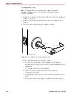
Adjust lockset to door thickness: Pull spring-loaded locking pin and rotate the threaded rose liner (G) until the door center mark aligns 
with center of the latch hole.

Ajuste el juego de la cerradura según el espesor de la puerta: Tire del pasador de bloqueo accionado por resorte y gire el revestimiento de la roseta roscado (G) 
hasta que la marca del centro de la puerta quede alineada con el centro del orificio del pestillo.
Ajustez le verrou à l’épaisseur de la porte : Tirez sur la goupille de verrouillage à ressort et faites pivoter la gaine de la rosette filetée (G) jusqu’à ce que le 
repère central de la porte s’aligne sur le centre du trou du verrou.

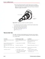
Make sure the latch tube 
prongs engage the chassis 
frame and that the latch 
tailpiece engages the retractor.

Asegúrese de que las patas del tubo 
del cerrojo se acoplen en el marco 
del chasis y de que la porción 
trasera del cerrojo se acople en el 
retractor.
Assurez-vous que les griffes du 
cylindre retiennent le logement du 
barillet en place et que la partie 
arrière du pêne dormant pénètre 
dans le rétracteur.

Factory preset for 1-3/4” (44.5mm) door.

Ajuste predefinido de fábrica para puerta de 1-3/4 pulg. (44,5 mm).
Préréglé en usine pour porte de 44,5 mm (1 3/4 po).

7

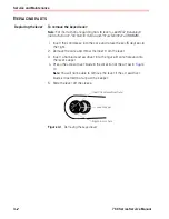
Temporarily remove the latch (M).

Retire el pestillo (M) en forma temporal.
Retirez temporairement le loquet (M).

6

Door center mark

Marca del centro de la puerta
Marque centrale de la porte

F

Once adjusted, make sure locking 
pin locks into rose liner.

Una vez ajustada, asegúrese de que la 
clavija de bloqueo se trabe en el 
revestimiento de rosa. 
Lorsque le tout est en place, assurez-vous 
que la goupille de verrouillages'immobil-
ise dans la rosette.

Rose locking pin

Pasador de bloqueo de la roseta
Goupille de verrouillage en rosette

Rotate Rose

Gire la roseta

Faites pivoter la rosette

Reinstall the latch.

Vuelva a instalar el pestillo.
Réinstallez le loquet.

K

(2x)

F

(2x)

J

L

H

P

O

D

B

A

A

For assistance or warranty information:

Call 1-855-365-2407 or visit www.bestaccess.com

Warning:


This  Manufacturer  advises  that  no  lock  can  provide  complete  security  by  itself.  This  lock  may  be  defeated  by 

forcible  or  technical  means,  or  evaded  by  entry  elsewhere  on  the  property.  No  lock  can  substitute  for  caution, 
awareness of your environment, and common sense. Builder’s hardware is available in multiple performance grades to 
suit the application. In order to enhance security and reduce risk, you should consult a qualified locksmith or other security 
professional.

Si desea ayuda o información sobre la garantia:

llame al 1-855-365-2407 ou visite www.bestaccess.com

Advertencia:

 Este fabricante have saber que no hay cerraduras que puedan proporcionar seguridad completa por si misma. 

Esta cerradura puede fallar forzandola o utilizando medios técnicos o entrando por otra parte del edificio. No hay cerraduras 
que puedan sustituir precaución, estar al tanto de su entorno y sentido común. Este fabricante también ofrece cerraduras de 
diferentes grados y rendimientos para ajustarse a su aplicación. Para mejorar la seguridad y reducer riesgos, usted debe 
consultar con un cerrajero especializado u otro profesional de seguridad.

Pour de l'aide ou des informations sur la garantie:

Vauillez appeler le 1-855-365-2407 ou visiter www.bestaccess.com

Advertissement:


Le fabricant tient à vous aviser qu'aucun verrou ne peut à lui seul offrir une sécurité complète. Ce verrou peut être 

mis hors d'état par la force ou des moyens techniques ou etre évité par l'utilisation d'une autre entrée sur la propriété. Aucun verrou 
ne peut remplacer la surveillance de votre enviornnenment et le bon sens. La quincaillerie pour le constructeur est offerte selon 
différents grades de performance pour différentes applications. Afin d'augmenter la sécurité et de rduire le risque, vous devriez 
consulter un serrurier qualifié ou un autre professionel de la sécurité.

N

(2x)

N

(2x)

N

(2x)

M

G

M

M

T80622_D

2/2

BEST is a trademark of dormakaba USA Inc. 

©

2021 All rights reserved.

Содержание 7KC Series

Страница 1: ...7KC GRADE 2 CYLINDRICAL LOCKS 7KC SERIES S E R V I C E M A N U A L...

Страница 2: ...echanical including photocopying recording or information storage and retrieval systems for any purpose without the express written permission of dormakaba USA Inc This document is distributed as is w...

Страница 3: ...AND PARTS LISTS 2 1 Function descriptions 2 2 Single keyed functions 2 2 Non keyed functions 2 3 Functions by ANSI designation 2 3 AB function chassis and trim entrance lock ANSI F109 2 4 Trim parts 2...

Страница 4: ...cores 3 10 Aligning the chassis and trim 3 11 Troubleshooting 3 12 INSTALLATION INSTRUCTIONS A 1 Position template 1 3 Bore two holes and install latch 1 3 Install boring jig and drill two 5 16 diame...

Страница 5: ...ever 3 2 Removing the plain lever or button lever 3 3 Reinstalling the lever keyed lever shown 3 4 Removing the inside rose with the screwdriver 3 5 Reinstalling the inside rose and rose liner 3 6 Rem...

Страница 6: ...Figures vi 7KC Series Service Manual...

Страница 7: ...FICATIONS AND STANDARDS The product complies with ANSI A156 2 Series 4000 Grade 2 standards California Administrative Code Title 19 and Title 24 Illinois Accessibility Standard The locks are listed by...

Страница 8: ...T56052 T56053 T56054 T56055 T56056 T56057 T56059 T56060 T56077 T56091 K08 Template for Door and Frame Preparation for 63K 73KC 83K 93K Cylindrical Locks with Small STK Strike K09 Template for Door and...

Страница 9: ...rea whenever you need help Before you call however please make sure you are where the 7KC Series Lock is and that you are prepared to give the following information what happened and what you were doi...

Страница 10: ...Getting Started 1 4 7KC Series Service Manual...

Страница 11: ...l 2 1 2 FUNCTIONS AND PARTS LISTS The following pages contain function descriptions for all 7KC Series Locks This chapter also includes an exploded diagram of a lock as well as diagrams of trim and ot...

Страница 12: ...ngle keyed 7KC function Outside Inside Latch Shadingindicatesthat theleverisfixed View looking down at thetopofthedoor AB Entrance ANSI F109 D Storeroom ANSI F86 Latchbolt operated by inside lever out...

Страница 13: ...outside lever when not locked Outside lever locked by inside button Outside lever unlocked by inside lever outside slotted button when rotated counterclockwise closing door Latchbolt operated by insid...

Страница 14: ...NSI F109 This diagram shows the AB function lock The chassis without trim and individual chassis parts are not available to order See the following pages for part numbers For levers see page 2 7 For r...

Страница 15: ...d strike boxes parts list 1 2 4 3 5 Item Nomen clature Part no Qty Description 1 8KS1 B25640 1 Standard steel strike box 2 6K 2 S A53761 1 Standard strike 3 N A A25359 2 Strike screw 4 6KS 3 Specify f...

Страница 16: ...rose liner 2 A55557 2 Through bolt screw 3 B56164 1 Outside rose not shown 1833754 1 Outside rose liner Figure 2 5 Buttons Buttons parts list 1 2 3 Finish Item1 Turnbutton assembly Item2 Slottedbutto...

Страница 17: ...Lever style 15 Lever style 16 1 2 3 6 5 4 7 8 9 Style Item Part no Specify finish Description 1 D56159 Plain lever handle 14 2 D56157 Button lever handle 3 D56158 Keyed lever handle 4 D56155 Plain lev...

Страница 18: ...arts list Viewlookinginsidethe end of the lever shaft End of the lever shaft 1 Item Part no Finish Description 1 D56156 15 Keyed lever for non interchangeable cylinders 626 Non interchangeable cylinde...

Страница 19: ...not shown B80113 6KL3 WF 2 3 4 4 B80194 6KL4 NF 3 3 4 not shown B80195 6KL4 WF 3 3 4 5 B80196 6KL5 NF 5 not shown B80197 6KL5 WF 5 Deadlocking latch with narrow face 1 Deadlocking latch with wide fac...

Страница 20: ...clature Part no Description 1 KD303 C55034 Drill jig 2 KD325 A01514 Strike plate locating pin 3 KD315 1350393 Faceplate marking chisel 1 1 8 2 1 4 not shown KD312 1487975 Faceplate marking chisel 1 2...

Страница 21: ...ig 2 KD325 A01514 Strike plate locating pin 3 KD315 1350393 Faceplate marking chisel 1 1 8 2 1 4 not shown KD312 1487975 Faceplate marking chisel 1 2 1 4 KD309 A54084 2 1 8 diameter chassis hole bit a...

Страница 22: ...Functions and Parts Lists 2 12 7KC Series Service Manual...

Страница 23: ...ins instructions for replacing components servicingandmaintainingcomponents and troubleshooting common problems To See page 3 2 3 5 3 8 3 10 3 11 Replace levers Replace roses Replace button assemblies...

Страница 24: ...rotate the key 15 degrees to the right 2 Remove the core and throw member from the lever 3 Insert a flat blade screwdriver into the figure 8 core hole and into the lever keeper 4 Press the screwdriver...

Страница 25: ...To remove the plain lever or button lever 1 Insert the knob keeper tool into the hole on the shaft of the lever as shown in Figure 3 2 2 Slide the lever off the sleeve Figure 3 2 Removing the plain l...

Страница 26: ...urn the levers to check that they operate smoothly 4 If the lever is keyed perform the steps below a For R function locks insert a screwdriver into the figure 8 opening and turn the locking mechanism...

Страница 27: ...lts 4 Slide the liner off the sleeve Save the liner To reinstall the inside rose 1 Align the holes in the liner with the holes prepared in the door as shown in Figure 3 5 2 Install the two through bol...

Страница 28: ...vers page 3 2 inside rose and rose liner page 3 5 2 Slide the chassis assembly out of the door 3 Retract the rose locking pin and rotate the rose and liner assembly until it is free from the hub See F...

Страница 29: ...onto the outside hub 3 Retract the rose locking pin and rotate the rose and liner assembly onto the hub until the assembly reaches the bottom of the threading 4 With the rose locking pin still retrac...

Страница 30: ...s frame and the latch tailpiece engages the retractor See Figure 3 8 6 Reinstall the following components inside rose and rose liner page 3 5 levers page 3 4 Replacing the button assembly To remove th...

Страница 31: ...ly from the locking bar as shown in Figure 3 9 1 Align the button tab with the top slot in the sleeve as shown in Figure 3 10 Figure 3 9 Removing the button assembly To reinstall the button assembly I...

Страница 32: ...e pin segment holes Note When cores are installed and exposed to harsh weather conditions silicone type lubricants can help displace moisture as well as spread into pin segment holes and other surface...

Страница 33: ...is frame and the latch tailpiece engages the retractor as shown in Figure 3 11 The outside rose and liner should also be flush with the door 3 If the chassis is not aligned with the latch or the outsi...

Страница 34: ...to its normal position Key spins freely but won t retract the latch or unlock the door Core doesn t fit into the lever core hole Button doesn t pop out as expected Latch doesn t retract There is bindi...

Страница 35: ...7KC Series Service Manual A 1 A INSTALLATION INSTRUCTIONS The following pages contain the Installation Instructions for 72KC 75KC Cylindrical Locks...

Страница 36: ...Installation Instructions A 2 7KC Series Service Manual...

Страница 37: ...c le bord parall le au bord de la porte Engage the jig with the latch tabs Enganche la plantilla con las pesta as del pestillo Engagez le gabarit avec les languettes du loquet Drill two 5 16 8mm holes...

Страница 38: ...la cerradura seg n el espesor de la puerta Tire del pasador de bloqueo accionado por resorte y gire el revestimiento de la roseta roscado G hasta que la marca del centro de la puerta quede alineada c...

Страница 39: ...0 E exploded diagrams see part numbers and drawings F faceplate marking chisel 2 10 to 2 11 function description for AB function lock 2 2 for D function lock 2 2 for L function lock 2 3 for N function...

Страница 40: ...utside rose 3 7 removing button 3 8 inside rose 3 5 keyed lever 3 2 lock chassis from the door 3 6 outside rose 3 6 plain lever or button lever 3 3 roses part numbers and drawings for 2 6 reinstalling...

Страница 41: ...T80621_C BEST is a trademark of dormakaba USA Inc 2021 All rights reserved...

Отзывы: