USER MANUAL 1.2 | B-FORTIS CC-PRIME SERIES
Berghof Automation GmbH | Arbachtalstrasse 26 | 72800 Eningen |
30
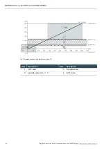
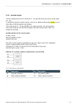
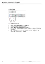
Example for counter: capture input or Z input
Fig. 11: counter with capture input
Pin
Designation
Pin
Designation
C1
Up, A (CNT0)
C3
–
C2
Down, B (CNT0)
C4
Capture (rise), Z (CNT0)
Counter CNT1 is not available in this configuration.
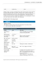
Data of the counter inputs
Data of the counter inputs
Feature
Value
Description
Number of counters
2
–
Signal voltage
(1): DC 15…28 V
(0): DC
–3…3 V
Pulse width at the valid level for at least 1 µs
Max. frequency
signal
counter
500 kHz
1 counts/s
For 100 kHz see specific installation
information.
At the maximum counter frequency the signal
transmitter must ensure an edge steepness of
at least 20 V/µs at the counter input.
Min. pulse width
10 µs
Per level
Counter resolution
32 Bit
–
Internal pull-up
3 k
Ω
–
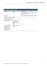
Installation information
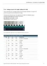
The counter inputs must be connected with shielded cables.
Supply voltage (24 V DC; GND) and signals of the transmitters must go through the same cable.
The SPS and the transmitter must use the same power supply.
Содержание B-Fortis CC-Prime S01
Страница 1: ...USER MANUAL 1 2 B Fortis CC Prime Series ...

