1
OWNER’S MANUAL
Model Number
79974
700304-1Subframe
700303-1 Drive Mechanism
104281
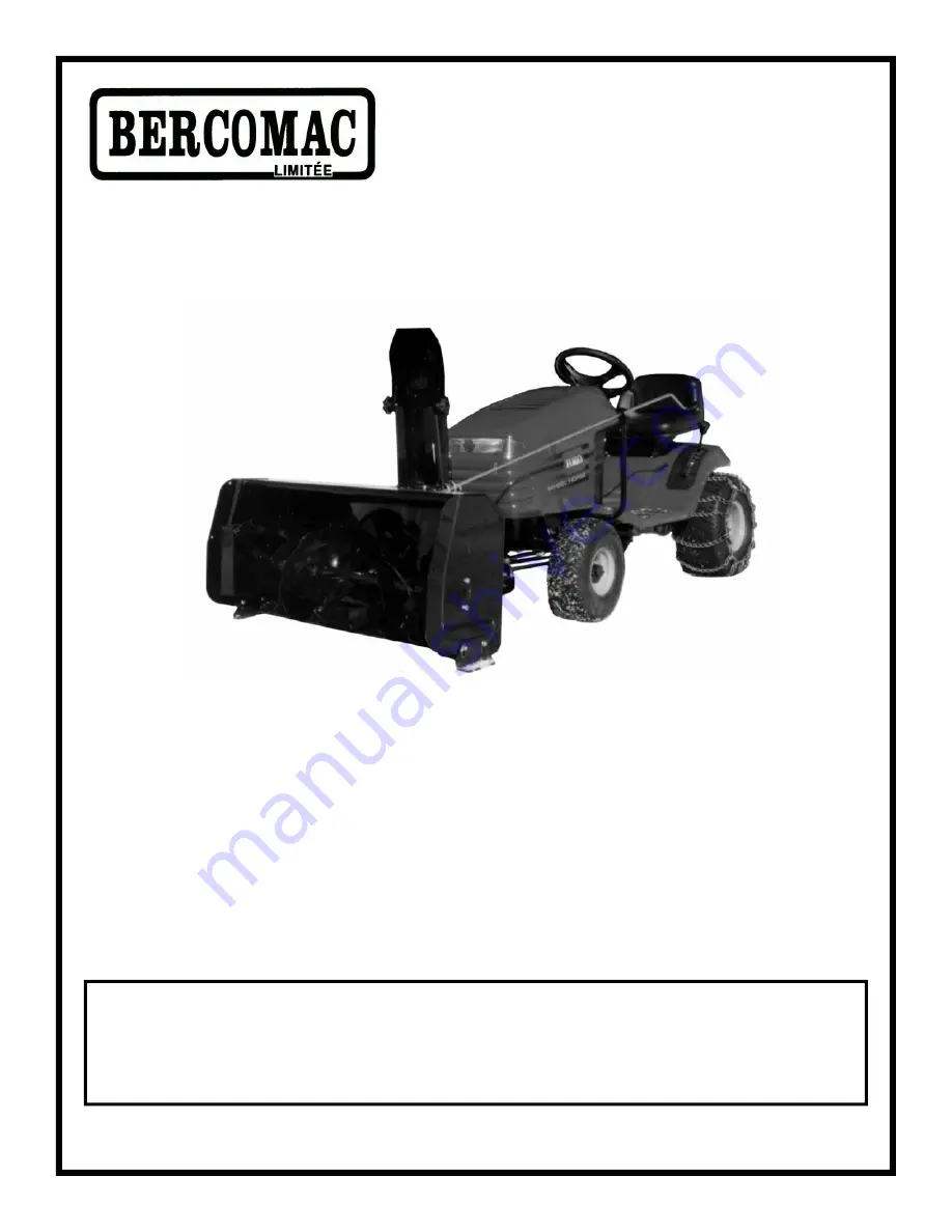
BERCO
COMPACT MOUNTING KIT
for
TORO HXL 1638
Tractors
F-11
* ASSEMBLY
* REPAIR PARTS
* OPERATION
* MAINTENANCE
CAUTION:
READ & FOLLOW ALL SAFETY RULES & INSTRUCTIONS
BEFORE OPERATING YOUR EQUIPMENT


