


02/ 2011
BENNING ST 720
29
or
- With correct mains voltage ("LN" and "LE" symbols on the display), press the
-key
6
to
start the RCD test.
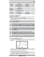
LN
LE
NE
Mains voltage
Flashing
Flashing
OFF
No mains voltage
OFF
Flashing
Flashing
Earth fault
- The BENNING ST 720 generates a fault current of 30 mA with positive (0°) or negative
(180°) initial polarity. The RCD will be tripped and the tripping time will be measured.
- If the tripping time is less than the limiting value (200 ms), a
will be shown next to the
tripping time.
- The test is considered to be passed, if "PASS" is shown on the display.
- Repeat the test with reversed initial polarity.
See figure 7:
Testing of RCD (I
ΔN
30 mA)
Note:
- By generating a fault current of 30 mA, it is proven that the RCD will trip when the nominal
fault current is reached. If the limiting value of the maximum contact voltage of 50 V is ex-
ceeded, the "UB > 50 V" symbol will be shown on the display and the testing will be stopped.
- When testing mobile RCDs, make sure that the mobile RCD is connected with a shock-proof
socket which is not protected by an own RCD.
Measurement might be influenced by:
- a possibly existing voltage between the protective conductor of the shock-
proof socket and earth
- leakage currents in the circuit behind the RCD
- further earthing equipment
- equipment which is connected behind the RCD and which will cause a
longer tripping time, e.g. capacitors or rotating machines
8.4 Testing three-phase test objects under operating conditions
Three-phase test objects are tested by means of the optional measuring adapters 16 A CEE,
three-phase, active (044140) or 32 A CEE, three-phase, active (044141).
- Connect the CEE plug of the test object with the CEE coupling of the measuring adapter and
connect the CEE plug of the measuring adapter to a protected supply mains (3 x 400 V, N,
PE, 50 Hz, 16 A/ 32 A).
- Connect the measuring signal cable of the measuring adapter with the mains connection
socket
K
of the BENNING ST 720.
- Connect the 4 mm safety plug of the test lead with alligator clip with the 4 mm safety socket
9
of the BENNING ST 720 and establish a connection with a metal part of the test object.
- Make sure that the test sample is protected and switch it on.
- Press the
key
7
to start the automatic testing procedure.
- If a contact voltage is applied to the metal part of the test object, measurement will be inter-
rupted and the following warning will be shown on the display: