Bender isoPV1685 Скачать руководство пользователя страница 1

Manual

EN

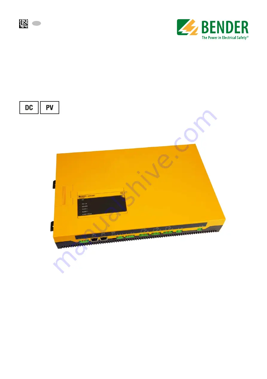
Insulation monitoring device 
with residual current monitoring (isoPV1685PFR only)
for unearthed DC systems 
for photovoltaic systems up to 1500 V 
isoPV1685: software version D409 v2.0x
isoPV1685P : software version D525 v2.0x
isoPV1685PFR: software version D366 v1.0x

isoPV1685-1685PFR_D00007_02_M_XXEN/10.2016

isoPV1685
isoPV1685P
isoPV1685PFR

Содержание isoPV1685

Страница 1: ...soPV1685PFR only for unearthed DC systems for photovoltaic systems up to 1500 V isoPV1685 software version D409 v2 0x isoPV1685P software version D525 v2 0x isoPV1685PFR software version D366 v1 0x isoPV1685 1685PFR_D00007_02_M_XXEN 10 2016 isoPV1685 isoPV1685P isoPV1685PFR ...

Страница 2: ... Straße 65 35305 Grünberg Germany Tel 49 6401 807 0 Fax 49 6401 807 259 E mail info bender de www bender de Bender GmbH Co KG All rights reserved Reprinting only with permission of the publisher Subject to change Photos Bender archives and bendersystembau archives ...

Страница 3: ...ddress setting and termination 13 2 5 Intended use 13 3 Function 15 3 1 Device features isoPV1685 isoPV1685P and isoPV1685PFR 15 3 2 Product description 15 3 3 Description of function 16 3 3 1 Insulation monitoring 17 3 3 2 Insulation fault location isoPV1685P FR 17 3 3 3 Residual current monitoring isoPV1685PFR 18 3 3 4 Self test 18 3 3 4 1 Self test after connection to the supply voltage 18 3 3 ...

Страница 4: ...ring 28 5 3 2 Commissioning flow chart insulation fault location isoPV1685P FR only 29 6 BMS and CAN bus 31 6 1 BMS bus 31 6 1 1 RS 485 interface with BMS protocol 31 6 1 2 Topology RS 485 network 32 6 1 3 BMS protocol 32 6 1 4 Commissioning of an RS 485 network with BMS protocol 33 6 1 5 Setting the BMS address 34 6 1 6 Alarm and operating messages via the BMS bus 34 6 1 6 1 Alarm messages 35 6 1...

Страница 5: ...ls and certifications 44 8 3 Ordering data 44 8 4 Characteristic curves 45 8 4 1 The measurable leakage capacitance depends on the insulation resistance 45 8 4 2 Response time for insulation measurement 45 8 4 3 Response time for residual current measurement isoPV1685PFR only 47 8 4 4 Example of alarms stored in the history memory 48 INDEX 49 ...

Страница 6: ...6 ...

Страница 7: ...soPV1685 and isoPV1685PFR This manual isintendedfor qualified personnelworking in electrical engineering and electronics The signal word indicates that there is a high risk danger that will result in elec trocution or serious injury if not avoided This signal word means that there is a medium risk of danger that can lead to death or serious injury if not avoided This signal word indicates a low le...

Страница 8: ...ed Bender devices Extended guarantee for Bender devices which includes an in house repair service or replace ment devices at no extra cost Telephone 49 6401 807 780 technical issues 49 6401 807 784 785 sales Fax 49 6401 807 789 E mail repair bender service de Please send the devices for repair to the following address Bender GmbH Repair Service Londorfer Strasse 65 35305 Grünberg 1 1 3 Field servi...

Страница 9: ...evices must only be stored in areas where they are protected from dust damp and spray and dripping water and in which the specified storage temperatures can be ensured 1 5 Disposal Abide by the national regulations and laws governing the disposal of this device Ask your supplier if you are not sure how to dispose of the old equipment The directive on waste electrical and electronic equipment WEEE ...

Страница 10: ...Important information 10 isoPV1685 1685PFR_D00007_02_M_XXEN 10 2016 ...

Страница 11: ...al standards and regulations must be complied with European standard EN 50110 can be used as a guide Only qualified personnel are permitted to carry out the work necessary to install commission and run a device or system Risk of electrocution due to electric shock Touching live parts of the system carries the risk of An electric shock Damage to the electrical installation Destruction of the device...

Страница 12: ...f touching live parts Switch off the mains voltage before opening the device In the event of an alarm message of the ISOMETER the insulation fault should be eliminated as quickly as possible If the ISOMETER is installed inside a control cabinet the insulation fault mes sage must be audible and or visible to attract attention When using ISOMETER s in IT systems make sure that only one active ISOMET...

Страница 13: ...sured insulation faults on the AC side inverter transformer isoPV1685PFR only Intended use also implies The observation of all information in the operating manual Compliance with test intervals In order to meet the requirements of applicable standards the equipment must be adjusted to local equipment and operating conditions by means of customised parameter settings Please heed the limits of the r...

Страница 14: ...Safety instructions 14 isoPV1685 1685PFR_D00007_02_M_XXEN 10 2016 ...

Страница 15: ... allowing fast disconnection isoPV1685PFR only Residual current response values IΔn for prewarning and alarm 1 5 A isoPV1685PFR only CT connection monitoring isoPV1685PFR only Device self test with automatic fault message in the event of a fault Alarm relays separately adjustable for insulation faults residual current faults and device errors isoPV1685PFR only Alarm relays separately adjustable fo...

Страница 16: ...larm relay K1 switches and the LED Alarm 2 lights The residual current is detected via an external measuring current transformer The r m s value is cal culated by summing up the AC component that are below the cut off frequency When the residual current exceeds the set alarm response value the corresponding alarm relay K2 switches and the as sociated LED Alarm IdN lights up All relevant measured v...

Страница 17: ...the alarm LEDs Alarm 1 resp Alarm 2 located on the pcb which are not accessible during normal operation will light up 3 3 2 Insulation fault location isoPV1685P FR For insulation fault location a suitable locating current is superimposed onto the faulty PV system with which EDS insulation fault locators can locate insulation faults isoPV1685P FR utilises an in ternal locating current injector with...

Страница 18: ... one measuring and test winding is required for this purpose For current transformer monitoring an appropriate signal is delivered via the test winding that is evaluated by the measurement winding 3 3 4 Self test 3 3 4 1 Self test after connection to the supply voltage Once connected to the supply voltage all internal measurement functions the components of the process control such as data and par...

Страница 19: ...t the alarm relay K2 21 22 24 is switched over K3 is not switched over 3 3 5 Assignment of the alarm relays K1 K2 K3 Relay assignment isoPV1685 P K1 switches when the value falls below the alarm response value Ran1 insulation resistance K2 switches when the value falls below the alarm response value Ran2 insulation resistance K3 switches in the event of a device or connection error Relay assignmen...

Страница 20: ...nd Acknowledgement timestamps are stored in the internal history memory The history data are copied from the internal EEPROM to the History csv file on the μSD card under the following conditions following device start up during operation once an hour when a compatible μSD card has been inserted For the evaluation of the history memory the Excel tool iso1685 History xlsx can be made available This...

Страница 21: ...M_XXEN 10 2016 4 Device overview 4 1 Dimensions SERVICE ALARM 2 ISOMETER isoPV1685 ON ALARM 1 PGH ON ALARM 3 I n 246 mm 125 mm 40 5 mm 40 75 mm 51 mm 368 mm 383 mm 401 5 mm 106 mm 64 mm 8 75 mm 5 2 mm 61 8 mm 76 6 mm 39 8 mm 55 7 mm ...

Страница 22: ...PFR with function 31 32 34 Output for device error LED Service 21 22 24 Output for Alarm insulation fault 11 12 14 Output for Alarm insulation fault E KE Connection E KE Connect both to PE A1 A2 Supply voltage DC24V Any polarity SERVICE ALARM 2 ISOMETER iso1685FR ON ALARM 1 SERVICE ALARM 2 ISOMETER isoPV1685 ON ALARM 1 PGH ON ALARM 3 I n LEDs ON Power On flashes PGH ON Insulation fault location is...

Страница 23: ...ied out Change BMS address SS8103 Set maximum leakage capacitance SS8103 Change measurement speed SS8103 Reset Alarms ST6101 Additionally you can read out e g alarms from the μSD card You can find a description of the DIP switch in chapter 7 1 Setting the permissible system leakage capacitance or measurement speed on page 39 Controls Function DIP switch SS8103 BMS termination A4 A0 Leakage capacit...

Страница 24: ...ion fault system earth measuring current transformer Lights continuously Also refer to the list of error codes on page 37 ALARM 1 yellow Insulation fault 1 prewarning Lights continuously when the insulation resistance falls below response value 1 RF Ran1 Connection fault earth Flashes ALARM 2 yellow Insulation fault 2 Alarm Lights continuously when the insulation resistance value falls below respo...

Страница 25: ...l installation Destruction of the device Before installing and connecting the device make sure that the installa tion has been de energised Observe the rules for working on electrical installa tions Warning of insulation monitoring devices that do not work correctly ConnecttheterminalsKEandEindividuallytotheprotectiveearthconductorPE Risk of injury from sharp edged terminals Risk of lacerations To...

Страница 26: ...ried out the device must be isola ted from the system for the test period Otherwise the device may be damaged Check proper connection Prior to commissioning of the installation check that the device has been pro perly connected and check the device functions Perform a functional test using an earth fault via a suitable resistance ISOMETER iso1685 US 6A 313234 111214 212224 6A 1A 1A BMS Master 2 PE...

Страница 27: ...2 x RJ 45 can be terminated using SS8102 A B S Connection to BMS bus RS 485 S shield connect one end to PE can be terminated with SS8100 k l kT lT isoPV1685PFR only Connection to measuring current transformer k l measurement winding kT lT test winding 31 32 34 Alarm relay K3 for internal device errors 21 22 24 Description of relay assignment according to device type see page 19 isoPV1685 only Alar...

Страница 28: ...no yes yes ja isoPV1685 not suitable Measuring current transformers to k l kT lT Connection or device error check connection Shall the factory setting be retained no yes Carry out settings via the CAN or BMS bus Alarm LEDs deactivated yes no Preset response value undershot possibly adjust Function test with a suitable resistance between system and earth Value 50 of the response value Ran2 Alarm LE...

Страница 29: ... Alarm relays switched yes no Set the EDS mode of the isoPV1685PFR to auto via the BMS bus Press the test button of the EDS46x 49x Is the faulty subcircuit being recognised correctly ADR xx k xx xxmA yes Shall other connected CTs be tested Are all CTs recognised correctly from EDS46x 49x no Check the CT wiring yes no yes Remove resistor and select another circuit downstream a measuring current tra...

Страница 30: ...Installation connection and commissioning of the device 30 isoPV1685 1685PFR_D00007_02_M_XXEN 10 2016 ...

Страница 31: ...SS8100 An RS 485 network that is not terminated is likely to get instable and may result in malfunctions Only the first and the last device in one line may be terminated Stub feeders in the network are not to be terminated The length of the stub feeders is restricted to 1 meter Fig 6 1 Wiring and termination of the BMS bus with SS8100 on the pcb or enclosure maximum length of the RS 485 network 12...

Страница 32: ...of bus nodes is restricted to 32 devices When more devices are to be connected Bender recommends to use a DI1 repeater 6 1 3 BMS protocol This protocol is an essential part of the Bender measuring device interface BMS bus protocol Data transmission generally makes use of ASCII characters Interface data are Baud rate 9600 baud Transmission 1 start bit 7 data bits 1 parity bit 1 stop bit 1 7 E 1 Par...

Страница 33: ... system the ISOMETER isoPV1685P can function as a substitute master with an BMS adress 1 e g 2 or 3 Slaves in the system can be adressed via the substitute master Fault causes may be Addresses are assigned twice A second master exists on the BMS bus Interference signals occur on the bus lines A defective device is connected to the bus Terminating resistors are not activated resp not connected 6 1 ...

Страница 34: ...6 1 6 Alarm and operating messages via the BMS bus Messages are transmitted to a maximum of 12 BMS channels All alarm and operating messages which may occur are described below DIP Schalter SS8103 Switch position BMS Adr A4 A3 A2 A1 A0 Up Off Down On 2 0 0 0 0 0 3 0 0 0 0 1 4 0 0 0 1 0 5 0 0 0 1 1 6 0 0 1 0 0 7 0 0 1 0 1 8 0 0 1 1 0 9 0 0 1 1 1 10 0 1 0 0 0 33 1 1 1 1 1 O A4 A3 A2 A1 A0 1 2 3 4 5 ...

Страница 35: ...rature coupling L Overtemperature coupling 11 Overtemperature coupling L Overtemperature PGH 12 Overtemperature of the locating current injector Channel occupied isoPV1685P FR only Alarm Channel Meaning Insulation resistance 1 Insulation resistance response value Ran1 Insulation resistance 2 Insulation resistance response value Ran2 Residual current IΔN 3 Residual current response value IΔn1 prewa...

Страница 36: ... will be generated again The error can also be reset by means of the acknowledgement command via the CAN bus 6 1 8 Starting the firmware update via the BMS bus The firmware can be updated via the BMS bus using the BMS Update Manager which can be obtained from Bender 6 2 CAN bus Communication via the CAN interface is descriped in a separate document The CAN bus can be ter minated with a 120 Ω termi...

Страница 37: ... a P 6 0 0 8 x 0 1 6 9 9 62 0x8006 Parameter Residual current measurement 9 63 0x8006 Parameter Locating current injector 9 64 0x8008 Parameter Voltage measurement 9 71 0x80FF System Program sequence insulation monitoring 9 72 0x80FF System Programsequenceresidualcurrentmeasurement 9 73 0x80FF System Program sequence locating current injector 9 74 0x80FF System Program sequence voltage measurement...

Страница 38: ...BMS and CAN bus 38 isoPV1685 1685PFR_D00007_02_M_XXEN 10 2016 ...

Страница 39: ...ownload software html These settings may only be changed when the PV voltage is switched off When the maximum system leakage capacitance Ce max is set to 2000 μF the upper limit of measuring range for the insulation resistance decreases from 1 MΩ to 50 kΩ DIP switch SS8103 segment 6 OFF 500 μF Ce max ON 2000 μF Ce max Switch position Up Off Down On DIP switch SS8103 segment 7 OFF Fast ON Slow Bend...

Страница 40: ...easurement off BMS isoPV1685PFR only Fault memory residual current measure ment off BMS isoPV1685PFR only Transformer monitoring on BMS Relay K1 11 12 14 N C operation BMS Relay K2 21 22 24 N C operation BMS Relay K3 31 32 34 N C operation isoPV1685P FR only EDS mode auto BMS isoPV1685P FR only PGH current 30 mA BMS isoPV1685PFR only Standby mode disconnection from the mains off BMS Reset to facto...

Страница 41: ...rmissible system leakage capacitance Ce 2000 μF 500 μF Response values for insulation monitoring Response value Ran1 Alarm 1 200 Ω 1 MΩ 10kΩ Response value Ran2 Alarm 2 200 Ω 1 MΩ 1kΩ Upper limit of the measuring range when set to Cemax 2000 μF 50 kΩ Relative uncertainty 10 kΩ 1 MΩ acc to IEC 61557 8 15 Relative uncertainty 0 2 kΩ 10 kΩ 200Ω 15 Response time tan see page 45 Hysteresis 25 1 kΩ isoP...

Страница 42: ...neend 2 core 0 6 mm2 z B J Y St Y2x0 6 Shield terminalS Terminating resistor can be connected term RS 485 120 Ω 0 5 W Device address BMS bus 2 33 2 CAN Protocol acc to SMA Bender specification V2 2 Frame format CAN2 0A11 bitidentifier Baud rate 500 kbit s Connection via 2 x RJ45 acc to CiA 303 1 connected in parallel Pin 1 CAN H Pin2 CAN L Pin3 7 CAN GND CAN identifier permanently set acc to the s...

Страница 43: ...AWG 24 8 Stripping length 15 mm Opening force 90 120 N Environment EMC EMC IEC 61326 2 4 Ed 1 0 Classification of climatic conditions acc to IEC 60721 Without solar radiation precipitation water icing Condensation possible temporarily Stationary use IEC 60721 3 3 3K5 Transport IEC 60721 3 2 2K3 Long time storage IEC 60721 3 1 1K4 Classification of mechanical conditions acc to IEC 60721 Stationary ...

Страница 44: ...DIN EN 61557 8 VDE 0413 8 IEC 61557 8 IEC 61557 9 IEC 61326 2 4 IEC 60730 1 DIN EN 60664 1 VDE 0110 1 UL1998 Software 8 3 Ordering data The data labelled with an are absolute values Type Responsevalue range Supply voltage Art No isoPV1685 425 200 Ω 1 MΩ DC 18 30 V B91065603 isoPV1685P 425 200 Ω 1 MΩ DC 18 30 V B91065604 isoPV1685PFR 425 200Ω 1 MΩ DC 18 30 V B91065600 ...

Страница 45: ...00007_02_M_XXEN 10 2016 8 4 Characteristic curves 8 4 1 The measurable leakage capacitance depends on the insulation resistance 8 4 2 Response time for insulation measurement 1 10 100 1000 0 0 5 0 5 5 5 0 Capacitance μF Fault resistance k ...

Страница 46: ...Technical data 46 isoPV1685 1685PFR_D00007_02_M_XXEN 10 2016 10 100 1000 0 4 1 0 2 0 4 0 10 0 20 0 40 0 100 0 200 0 1 μF 500 μF 2000 μF R k an s isoPV1685 F ...

Страница 47: ...47 isoPV1685 1685PFR_D00007_02_M_XXEN 10 2016 8 4 3 Response time for residual current measurement isoPV1685PFR only 0 5 0 55 0 6 0 65 0 7 0 75 0 8 0 85 0 9 0 95 1 0 5 0 2 0 1 1 kHz 3 kHz 6 kHz I N A t an s isoPV1685 ...

Страница 48: ...2 13 45 02 05 2012 3 5 12 10 07 Idx 231 ID 43 Insula on fault 200 200 Ω None 27 4 12 13 59 27 4 12 13 59 Index ID Alarm Min Max Unit Start Time Test Ack Time Stop Time Index in the history memory ID Unit Alarm type Message due to Test Minimum value during alarm Minimum value during alarm Start me of the message Acknowledge me of the message End me of the message ...

Страница 49: ...puts of the inverter 20 Micro SD card 16 O Operating controls DIP switch 23 Operating status messages 35 Ordering information 44 P Parameterisation of insulation fault loca tion 18 PCB component layout 48 Product description 15 R Resetting error messages 36 Residual current monitoring 18 Response time Differential measurement method 47 Insulation measurement 45 RS 485 interface 31 RS 485 network C...

Страница 50: ...50 ...

Страница 51: ......

Страница 52: ... KG P O Box 1161 35301 Grünberg Germany Londorfer Straße 65 35305 Grünberg Germany Tel 49 6401 807 0 Fax 49 6401 807 259 E mail info bender de www bender de Fotos Bender Archiv und bendersystembau Archiv BENDER Group ...

Отзывы: