


Settings
Settings
iso685-D-B_D00177_05_M_XXEN/07.2017
36
10.1
(1.9.1.4) Function
The parameters for the function of the digital inputs of the ISOMETER® can be set
differently:
10.1
(1.9.2) Digital 2
Refer to
10.1
(1.9.3) Digital 3
Refer to
•off
Digital input without function
•TEST
Device self test
•RESET
Reset of fault and alarm messages
•Deactivate
device
The device DOES NOT measure the insulation resistance, the message
Device inactive
appears on the display.
The IT system is NOT being monitored!
The device uncouples itself from the system to be monitored through
an internal system isolating switch.
•Start initial
measurement
All recorded measurements are discarded and a new measurement is
started
10.1
(1.10) Outputs
The ISOMETER® provides a total of six outputs.
The following parameters can be set for the outputs:
10.1
(1.10.1) Relay 1
The following parameters can be set for each relay:
10.1
(1.10.1.1) TEST
The functional test of the relay can be activated or deactivated. This only applies to the
manual test and not to the cyclic device self test:
10.1
(1.10.1.2) Relay mode
The relay mode can be adapted to the application:
10.1
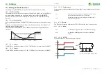
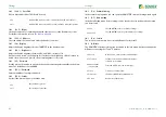
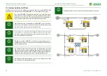
(1.10.1.3) Function 1
Up to three functions can be assigned to one output. The functions are linked to an OR
operator:
•on
The manual test checks the switching function of the relay
•off
The manual test does not check the switching function of the relay
•N/C
Normally closed- N/C operation contacts11-12-14 / 21-22-24
(in fault-free condition, the alarm relay is energised).
•N/O
Normally opened - N/O operation contacts 11-12-14 / 21-22-24
(in fault-free condition, the alarm relay is de-energised).
≥ 1
Response
Function 1
Function 2
Function 3


