18
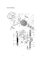
3.5.5.- PUMP - Refer to Fig 3.5
a)
Drain hydraulic tank as described in 3.5.2.
b)
Disconnect H.P. Feed pipe as described in 3.5.3.
c)
Disconnect the suction hose (Item 21) at both swivel connections at the Tank (Item 22) and
the Pump (Item 13).
d)
Remove and retain the 4 off Cap Screws (Item 14) securing the pump (Item 11) to the
Pump Conversion Plate (Item 26)
e)
Withdraw the Pump away from the Pump Conversion Plate taking care to retain the nylon
insert between the coupling halves.
f)
Where a pump replacement is required it is necessary to remove the drive coupling half from
the pump shaft by folding back the locking tab on the Tab Washer and removing the Nut. The
coupling half will usually require a puller for removal as it is prone to locking on its taper. The
port connectors (Items 9 & 12) must also be removed.
NOTE -
Refitting the pump is the reverse of the above, however it is recommended that new Bonded
Seals (Item 10) are fitted, taking care to ensure that the port adaptors are not damaged
.
3.5.6. - FAN - Refer to Fig 3.5.
a)
Remove the pump as described in 3.5.5.
b)
Remove the Valve Block as described in 3.5.3.
c)
Remove 3 off Nuts (Item 16) and Washers (Item 17) and withdraw the Pump Plate (Item 18)
to
reveal the Fan and Drive Coupling half.
d)
Slacken the Grub Screw (Item 7) securing the Drive Coupling Half (Item 8) and slide off the
shaft.
e)
Slacken off the 2 off Grub Screws securing the Fan (Item 6) to the Shaft Extension, and slide
off the Fan. Retain the Shaft Key.
Содержание Major 30-140
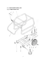
Страница 22: ...22 4 3 PARTS IDENTIFICATION LISTS Fig 3 1 FRAME CHASSIS ASSY ...
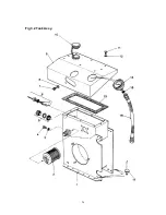
Страница 24: ...24 Fig 3 2 Tank Assy ...
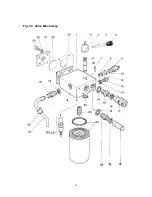
Страница 26: ...26 Fig 3 3 Valve Block Assy ...
Страница 28: ...28 Fig 3 4 Cooler Assy ...
Страница 30: ...30 Fig 3 5 Pump Assy ...
Страница 32: ...32 Fig 3 6 P O D Assy ...
Страница 34: ...34 Fig 3 7 Hose Assy ...


