HOUSING
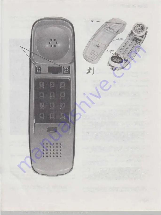
SCREWS
• • •• • •
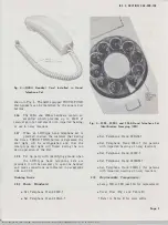
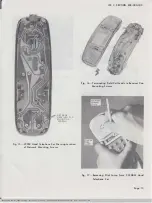
Fig. 6-Location of Housing Screws
ISS 2, SECTION 502-303-102
MOUNTING
SCREW
HOLES
MOUNTING
SCREWS (4)
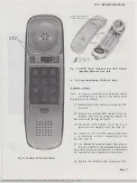
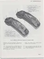
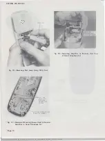
Fig. 7-2220C Hand Telephone Set With Chassis
Assembly Removed from Deck
A. Tip Party Identification (0-Kits of Parts)
D-180824 (220AL)
3.04
If tip party identification is required, install
a D-180824 Kit of Parts in the 220AL hand
telephone set as follows.
(1) Remove shell from handset, paragraphs 3.01
and 3.02
(2) Remove the t·xisting 2270 adapter from the
handset cord jack by grasping adapter on
both sides and puJling outwards.
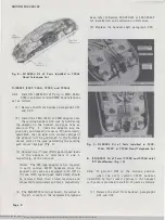
(3) Install the 227C adapter from the kit of
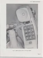
parts into the handset cord jack (Fig. 8).
(4) Connect the
(Y)
and (BK) spade-tipped leads
to terminals A and 4, respectively, of the
network (Fig. 8).
(5) The 840362776 terminal board, furnished in
the kit, mounts in the associated telephone
base, refer to Section 502-303-101 or 502-322-400
for installation and connection information.
(6) Replace the handset shell, paragraph 3.03.
Page 7
SSP
502-303-10l-i02_1979-12-Q7.jpg Scanned by Frank Harrell, (Cowboy Frank) Castle Rock, Colorado Feb 07,2012 13:28:03

