background image

SECTION  502-303-1 02 

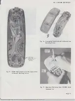
with  the  lip  of  the  grommet  protruding  outside 
the  assembly. 

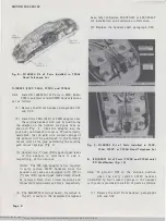
(5)  Place  the  receiver  unit  in  the  coil  assembly 

(Fig.  12). 

(6)  With  the  receiver  unit  in  place  in  the  coil 

assembly,  install  the  gasket  on  top  of  the 

receiver unit (Fig.  13).  Place complete assembly 

in  the  chassis  assembly  receiver  cup. 

In 

order  to  pro perly  insert  the  receiver 

unit  with  the  receiver  coil  into  the 

receiver  cup,  hold  handset  in  an  upright 

vertical  position  with  the  varistor 

across  the  receiver  unit  at  the 
top. 

Carefully  place  unit  in  the 

receiver  cup  and  snap  retainer 
to  the  chassis  assembly  receiver 
cup  (Fig.  14). 

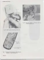
(7)  Loosen  the  two  (2)  network  receiver  cup 

mounting  screws  (Fig.  15)  on  back  side  of 

the  receiver  cup. 

Terminate  one  (1)  of  the 

black  (BK)  coil  leads  under  each  screw  (Fig. 
16). 

(8)  Reassemble  the  handset. 

(9)  Install  the  card  (Fig.  11)  which  identifies  a 

coil  equipped  handset  in  location  where  the 

cover  above  the  dial  was  removed.  Place  the 
(clear)  card  retainer  over  the  card. 

4. 

MAINTENANCE 

4.01 

Field  maintenance  of  these  hand  telephone 
sets is  limited to  the replaceable components 

listed  in  the  ordering  guide,  paragraph  2.10. 

4.02 

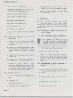
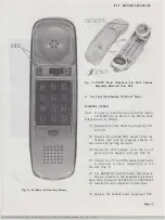
To  replace  a  dial  lamp  in  the  220A,  220AM, 

2220B, or 2220BM hand telephone set, remove 

the  cover  (Fig.  1).  A  KS-6320  orange  stick  can 
be  used  to  remove  the  lamp  (Fig.  17). 

Exercise 

caution  to  prevent  the  lamp  from  flying 
out  of  the  socket  in  a  dangerous  manner. 

In  early  production  handsets  use  a  553A  tool  to 

remove  the  lamp  from  its  vertical  position  (Fig. 

18). 

Note: 

Lamps carried for maintenance reasons 

should  be  53A  since  both  early  and  current 
production  handsets  accommodate  this  type. 

Page  1 0  

4.03 

To  replace  the  315-type  amplifier  in  226A 
or  2226A  handsets,  proceed  as  follows. 

(1)  Remove  shell  from  handset,  paragraphs 3.01 

and  3.02. 

(2)  Remove  the  network  receiver  cup  mounting 

screw  and  the  three  (3)  315-type  amplifier 

network  connecting  screws  (Fig.  19).  Carefully 
raise  the  flexible  circuit  boa�d  (network)  and 

remove  the  amplifier  receiver  cup  mounting 

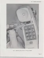
screw  (Fig.  20).  Release  the  amplifier  spring 

catch  by  depressing  with  a  KS-21107L1  or 
equivalent  releaser  as  shown  in  Fig.  21, and lift 

amplifier  out. 

(3)  Install  replacement  amplifier  in  reverse 

order  used  in  removal  and  reassemble  of 

handset. 

4.04 

To  replace  a  transmitter  or  receiver  unit  in 
220C, 226A, 2220C, or 2226A handset, proceed 

as  follows. 

(1)  Remove  shell  and  chassis  from  handset 

paragraphs  3.01,  3.02  and  Fig.  7. 

(2)  Twist  and  lift  off  the  transmitter  and/or 

receiver  unit,  retainer,  and  grommet  from 

the  cup  on  the  chassis. 

(3)  Separate the defective unit from the grommet 

and  retainer. 

(4)  Install  replacement  unit  in  reverse  order 

used  in  removal  and  reassemble  of  handset. 

In 

order  to  properly  insert  the  receiver 

unit  into  the  receiver  cup,  hold  handset 
in  an  upright  vertical  position  with 

the  varistor  across  the  receiver  unit 
at  the  top. 

Carefully  place  unit 

in  the  receiver  cup  a n d   snap 

retainer  to  the  chassis  assembly. 

5. 

CONNECTIONS 

5.01 

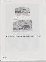
To  restrict  the  dial  on  the  220A,  220AL 

(early  version),  or  220AM  hand  telephone 

set,  place  a  strap  between  the  pulsing  contacts  as 
shown  in  Fig.  22.  On  the  220AL  (current  version) 
place  a  strap  between  the  two  (2)  screws  located 
on  the  flexible  circuit  board  above  the  dial.  In 
the  220C or  226A place an  insulated  strap between 

BSP S02-303-102-i02_1979-12-10.jpg  Scanned by Frank  Harrell, (Cowboy Frank) Castle Rock. Colorado  Feb 07,2012  13:29:51 

Содержание 220

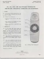
Страница 1: ...with other components and apparatus to make up a complete telephone set Refer to Table A for identification of associated apparatus RECALL BUTTON 2 02 These handsets are presently used with the TRIMLINE telephone Transaction Elevator Conference and some DESIGN LINE telephone sets 2 03 They consist primarily of a plastic deck and shell a dial flexible circuit board network handset cord jack transmi...

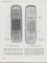
Страница 2: ...ge 2 315 TYPE AMPLIFIER VOLUME CONTROL NOTE RECALL SWITCH 226A HAND SET SAME EXCEPT HAS ROTARY DIAL Fig 3 2226A Hand Telephone Set transformer or equivalent 6 volt supply The 220C 220AL 226A 2220C and 2226A handsets are equipped with light emitting diodes LED for dial illumination Power to light these dials is supplied by CO battery over the incoming line and no local power is required The 220C 22...

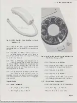
Страница 3: ...e LED type hand telephone sets are provided it will be necessary to open the handset and make connections as indicated in paragraphs 3 04 and 3 05 Ordering Guide 2 09 Basic Handsets Set Telephone Hand 220C t Set Telephone Hand 220AL t ISS 2 SECTION 502 303 102 Fig 5 220C 220AL and 226A Hand Telephone Set Identification Stamping LED Set Telephone Hand 220AM t Set Telephone Hand 226A t for persons w...

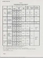
Страница 4: ...AD2 AD3 D4BU ACl AC1P 630A AC1P AD1 D5AL H4DU 231B AC1 AClP 630A AC1P AD2 D4BU AC2 AC2P 630A AC2P H4DU 231B AD2 AD2 AD3 D4BU AC1 AClP 630A AC1P AD1 D5AL H4DU 231B AC1 AClP 630A AC1P AD2 D4BU AC2 AC2P 630A AC2P H4DU 231B AD2 AD2 AD3 D4BU AC1 AC1P 630A AClP ADl D5AL H4DU 231B ACl AClP 630A AClP AD2 D4BU AC2 AC2P 630A AC2P H4DU 231A AD2 AD2 AD3 D4BU Note 1 All TRIMLINE components and apparatus are or...

Страница 5: ...060 Aqua Blue 62 841376825 840431621 818850620 841375587 P 88E062 Brown 104 841376833 840431100 818850109 841375595 P 88E010 Rust 124 841376882 840431126 818850125 841375603 P 88E012 Note These are the only recommended deck and shells to be replaced in field SSP 502 303 102 i02_1979 12 0S jpg Scanned by Frank Harrell Cowboy Frank Castle Rock Colorado Feb 07 2012 13 27 21 SHELL DECK 220C 226A 2220C...

Страница 6: ...26A only Page 6 Equipped with a recall switch to make repeated calls without hanging up handset Polarity Guard factory provided 2220C and 2226A only 3 INSTALLATION 3 01 The plastic deck and shell of these handsets are held together by two screws located under the cover above the dial Fig 6 If necessary to open hand telephone set refer to paragraphs 3 02 and 3 03 3 02 Removal of Hand Telephone Set ...

Страница 7: ...e t xisting 2270 adapter from the handset cord jack by grasping adapter on both sides and puJling outwards 3 Install the 227C adapter from the kit of parts into the handset cord jack Fig 8 4 Connect the Y and BK spade tipped leads to terminals A and 4 respectively of the network Fig 8 5 The 840362776 terminal board furnished in the kit mounts in the associated telephone base refer to Section 502 3...

Страница 8: ...he network Note The 282 type adapter is not required in early version 2220C handsets since the handset cord jacks are equipped with W or Y and BK spade tipped leads which should be removed from their stored locations and connected to terminals A and B or 4 respectively 4 The 840362776 terminal board furnished in the kit mounts in the associated telephone Page 8 base refer to Section 502 303 101 or...

Страница 9: ...prings of the adapter will be positioned in the formerly vacant slots ISS 2 SECTION 502 303 1 02 of the jack paralleling the existing gold contact spring Fig 9 4 Remove the screw from the flexible circuit tab network at receiver terminal C Insulate the tab 5 Insulate the shank portion of the BK adapter spade tipped lead and connect to the receiver terminal vacated by the flexible circuit tab 6 Con...

Страница 10: ...handsets accommodate this type Page 1 0 4 03 To replace the 315 type amplifier in 226A or 2226A handsets proceed as follows 1 Remove shell from handset paragraphs 3 01 and 3 02 2 Remove the network receiver cup mounting screw and the three 3 315 type amplifier network connecting screws Fig 19 Carefully raise the flexible circuit boa d network and remove the amplifier receiver cup mounting screw Fi...

Страница 11: ... TIP SHANK AT TERMINAL C 13 INSULATED FLEXIBLE CIRCUIT TAB NETWORK Fig 1 0 t2220C or 2226A Hand Telephone Set Modified for RFI terminals 1 and 2 on the network The dial will remain in the handset after being restricted in all cases 5 02 For dial restriction of a TOUCH TONE dial equipped hand telephone set without a polarity guard reverse tip and ring in telephone base and leave dial in handset Not...

Страница 12: ...Kit of Parts and Receiver Unit Fig 12 Receiver Unit Installed in Coil Assembly Page 12 Fig 13 Receiver Unit and Gasket Installed in Coil Assembly Fig 14 Field Coil Installed in Receiver Cup of Chassis Assembly SSP S02 303 102 i02_1979 12 12 jpg Scanned by frank Harrell Cowboy Frank Castle Rock Colorado Feb 07 2012 13 30 26 ...

Страница 13: ...ork Mounting Screws ISS 2 SECTION 502 303 102 Fig 16 Terminating Field Coil Leads to Receiver Cup Mounting Screws Fig 1 7 Removing Dial Lamp from 22208M Hand Telephone Set Page 1 3 SSP S02 303 102 i02_1979 12 13 jpg Scanned b y Frank Harrell Cowboy Frank Castle Rock Colorado Feb 07 2012 13 31 48 ...

Страница 14: ...EWS NETWORK RECEIVER CUP MOUNTING SCREW Fig 19 Location of Mounting Screws Used to Connect Amplifier in Hand Telephone Set Page 1 4 Fig 20 Fastening Amplifier t o Receiver Unit Cup of Hand Telephone Set BSP S02 303 102 i02_1979 12 14 jpg Scanned by Frank Harrell Cowboy Frank Castle Rock Colorado Feb 07 2012 13 32 04 ...

Страница 15: ...SS 2 SECTION 502 303 1 02 Fig 2 1 Releasing Spring Catch on 3 15 Type Amplifier Page 1S SSP S02 303 102 i02_1979 12 15 jpg Scanned by Frank Harrell Cowboy Frank Castle Rock Colorado Feb 07 2012 13 32 25 ...

Страница 16: ...AND 220 AM HAND TELEPHONE SETS 8 220AI CURRI NT VE RSION HAND TELEF HONt SET Fig 22 Restricting Dial of 220A MD 220AL Early Version or 220AM Hand Telephone Set Page 16 SSP S02 303 102 i02_1979 12 16 jpg Scanned by Frank Harrell Cowboy Frank Castle Rock Colorado Feb 07 2012 13 32 46 ...

Страница 17: ...I NOTE PROVIDED WITH 220AM HANDSET ONLY OP DIAL PULSE CONTACTS ISS 2 SECTION 502 303 1 02 RECEIVER TRANSMITTER DIAL UNIT UNIT J I I OP I T I I 4 l 1 B I AG I I I Fig 23 Schematic of 220A MD and 220AM Hand Telephone Set Page 1 7 BSP 502 303 102 i02_1979 12 17 jpg Scanned by Frank Harrell Cowboy Frank Castle Rock Colorado Feb 07 2012 13 33 13 ...

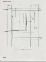
Страница 18: ...T UNIT x l OP RING X I I r I I I I I I I I 4 1l 1 L__ 8 T TIP I I I I I s I I I I 1Th DP OIAL PULSE CONTACTS Fig 24 Schematic of 220C Hand Telephone Set Page 18 BSP 502 303 102 i02_1979 12 18 jpg Scanned b y Frank Harrell Cowboy Frank Castle Rock Colorado Feb 07 2012 13 33 28 ...

Страница 19: ... SECTION 502 303 102 NETWORK DP DIAL PULSE CONTACTS RECEIVER TRANSMITTER UNIT UNIT Fig 25 Schematic of 220AL Hand Telephone Set DIAL DP Page 19 BSP 502 303 102 i02_1979 12 19 jpg Scanned by Frank Harrell Cowboy Frank Castle Rock Colorado Feb 07 2012 13 33 49 ...

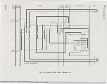
Страница 20: ...LSE CONTACT RCVR UNIT 1 9 3 I 8 TRMTR UNIT A JA 1 8 HLl Fig 26 Schematic of 226A Hand Telephone Set BSP 502 303 102 i02_1979 12 20 jpg Scanned by Frank Harrell Cowboy Frank Castle Rock Colorado Feb 07 2012 13 34 03 315A AMPLIFIER 1_ T eJ _f_r f L I _j 1HE DIAL r 1 oPt s 5 Ill 0 z 0 w 0 If 0 ...

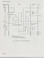
Страница 21: ... 2220BM HANDSET ONLY NETWORK 1 ISS 2 SECTION S02 303 1 02 RECEIVER RANSMITTER DIAL I I UNIT UNIT I I U Tl I I I I I n l3 0 2 GI I I 5 n Fig 27 Schematic of 22208 MD and 2220BM Hand Telephone Set Page 21 BSP 502 303 102 i02_1979 12 21 jpg Scanned b y Frank Harrell Cowboy Frank Castle Rock Colorado Feb 07 2012 13 34 23 ...

Страница 22: ...AND STORED NOTE THESE LEADS ARE FURNISHED IN EARLY VERSION 2220C HANDSETS ONLY RECEIVER UNIT 0 DIAL 2 L 5 TRANSMITTER UNIT _ 4 3 Fig 28 Schematic of 2220C Hand Telephone Set BSP 502 303 102 i02_1979 12 22 jpg Scanned by Frank Harrell Cowboy Frank Castle Rock Colorado Feb 07 2012 13 34 37 ...

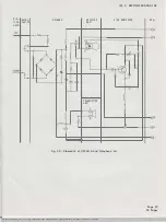
Страница 23: ...ITCH UNIT JACK 2 TIP rl Ji5 _______ 0 7 l I I r RING 1 1 t __ 5 I I TRANSMITTER UNIT A l l B 4 6 70 0 3 v Fig 29 Schematic of 2226A Hand Telephone Set BSP S02 303 102 i02_1979 12 23 jpg Scanned by Frank Harrell Cowboy Frank Castle Rock Colorado Feb 07 2012 13 34 59 Page 23 23 Pages ...

Отзывы: