background image

INTUITY CONVERSANT System Version 6.0 
MAP/100 New System Installation  

585-310-176  

Issue 3.0

June 1997

Cable Connectivity 

Page D-12

Connecting the Lucent I

NTUITY

 Multi-Port Card to a Distant Data Module via a 

D

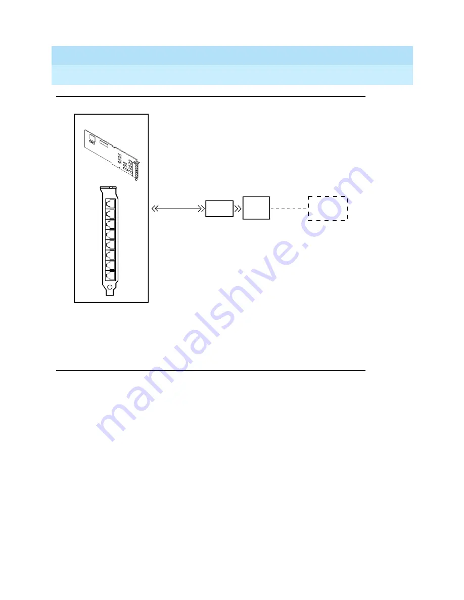
Figure D-9.

Connecting the Lucent I

NTUITY

 Multi-port Serial Card to a Distant

Data Module via a 7400A Data Module

Distant

data module

7400B

7400A
data
module

DTE
Adapter

14’

modular

cable

(provided)

Multi-port

circuit card

4conn-17 LJK 032696

Содержание Lucent Technologies INTUITY CONVERSANT MAP/100

Страница 1: ...INTUITY CONVERSANT System Version 6 0 MAP 100 New System Installation 585 310 176 Comcode 108037771 Issue 3 0 June 1997 ...

Страница 2: ... 68 of the FCC Rules It is identified by FCC registration number AS593M 11185 MF E Part 68 Answer Supervision Signaling Allowing this equipment to be operated in a manner that does not provide proper answer supervision signaling is in violation of Part 68 rules This equipment returns answer supervision signals to the public switched network when Answered by the called station Answered by the atten...

Страница 3: ...vity and Pinout Information xi To Locate Specific Topics xi Conventions Used in This Book xi Terminology xii Terminal Keys xv Screen Displays xv Other Typography xvi Safety and Security Alert Labels xvii Related Resources xviii Documentation xviii Electronic Updates to This Book xviii Training xviii How to Comment on This Book xix Disclaimer xix 1 Getting Started 1 1 Overview 1 1 Purpose 1 1 Site ...

Страница 4: ...t Attachment Limitations 1 9 Points of Demarcation 1 10 LAN Connectivity Demarcation 1 10 INTUITY CONVERSANT Script Builder FAX Actions Demarcation 1 10 Maintaining System Security 1 11 Password Security 1 11 System Security 1 11 Getting Help with the Installation 1 11 System Help Screens 1 11 2 Unpacking the MAP 100 and Installing Nonassembled Hardware 2 1 Overview 2 1 Purpose 2 1 Unpacking the M...

Страница 5: ...ing T1 Circuit Cards to a CSU 3 10 Connecting Asynchronous Devices 3 11 Using COM1 3 11 Using the 8 Port Asynchronous Circuit Card 3 11 Asynchronous Circuit Card EQUINOX Megaport 8C5 8 Port Serial I O Board 3 11 Connecting The MAP 100 to a Synchronous Host 3 12 PC XL Synchronous I O Card 3 12 FIFO SIB Synchronous Host Circuit Card 3 12 Host Cable Specifications 3 13 Connecting the LAN Circuit Card...

Страница 6: ...odem to the Platform 4 7 Configuring the 3820 Modem 4 8 Powering Up the System 4 9 Verifying the Intake Voltage 4 9 Connecting the System to the AC Power Supply 4 9 5 Verifying System Status 5 1 Overview 5 1 Purpose 5 1 Verifying Controlled Applications 5 2 Viewing Feature License Values 5 2 Feature Test Script Package 5 4 Feature Test Script Package Prerequisites 5 4 Setting Up the Feature Test S...

Страница 7: ... A 3 B Troubleshooting Procedures B 1 Overview B 1 Purpose B 1 Repairing Power Up Troubles B 2 Repairing Boot Up Troubles B 4 Repairing System Installation Upgrade Set Up Troubles B 7 C Pinouts C 1 Overview C 1 Purpose C 1 Pinouts for the Tip Ring Circuit Card C 2 Pinouts for Asynchronous Connections C 7 Pinouts for Peripheral Devices C 9 D Cable Connectivity D 1 Overview D 1 Purpose D 1 Slot Loca...

Страница 8: ...TY COM1 to a 715 Terminal or Other DCE Device D 8 Connecting the Lucent INTUITY Multi Port Card to Customer Equipment via a Modem D 9 Connecting the Lucent INTUITY Multi Port Card to a Terminal via ADUs D 10 Connecting the Lucent INTUITY Multi Port Card to a Distant Data Module via a 7400A Data Module D 11 Making a Direct Connection from the Lucent INTUITY Multi port Card to a 615 Terminal or Othe...

Страница 9: ... to the MAP 100 platform and the INTUITY CONVERSANT system and most of its optional features Intended Audiences This book is intended primarily for the on site technical personnel who are responsible for installing the system and performing initial administration and acceptance testing Secondary audiences include the following from Lucent Technologies Field support Technical Service Organization T...

Страница 10: ...oft MS MS DOS Internet Explorer and Excel are registered trademarks and Windows is a trademark of Microsoft Corporation Truevoice is a registered trademark of AT T UnixWare is a registered trademark of The Santa Cruz Operation Inc UNIX is a registered trademark of UNIX System Laboratories Inc Novell is a registered trademark of Novell Inc ORACLE ORACLE Terminal OBJECT SQL SQL FORMS SQL Menu SQL Ne...

Страница 11: ... installing a non ALT system see Appendix C Building a System in INTUITY CONVERSANT System Version 6 0 MAP 100 Maintenance 585 310 179 for instructions For a Quick Reference If you want a quick reference Appendix A System Installation Checklist contains a checklist of procedure titles These titles are listed in the order in which you must perform them Also included are references to where you will...

Страница 12: ... press is shown as Enter y to continue The word select means to move the cursor to the desired menu item and then press For example an instruction to move the cursor to the start test option on the Network Loop Around Test screen and then press is shown as Select Start Test The INTUITY CONVERSANT system displays windows screens and menus Windows and screens both show and request system information...

Страница 13: ...hard disk s space on your primary hard disk for the UNIX System After you press ENTER you will be shown a screen that will allow you to create new partitions delete existing partitions or change the active partition of your primary hard disk the partition that your computer will boot from WARNING All files in any partition s you delete will be destroyed If you wish to attempt to preserve any files...

Страница 14: ...dary hard disk If you choose to use a partition of your secondary hard disk you will be shown a screen that will allow you to partition your secondary hard disk WARNING All files in any partition s you delete will be destroyed If you choose to create a UNIX System partition on your secondary hard disk it must be at least 40 MBs Your Options are 1 Do not use a partition of the secondary hard disk f...

Страница 15: ...tion keys on your terminal PC or system screens also known as soft keys are represented as square boxes followed by the function or value of that key enclosed in parentheses For example an instruction to press function key 3 is shown as Press Choices Keys that you press on your telephone keypad are represented as square boxes For example an instruction to press the first key on your telephone keyp...

Страница 16: ...nu you would then select the Alarm Management screen Screens shown in this book are examples only The screens you see on your machine will be similar but not exactly the same Other Typography Commands and text you type in or enter appear in bold type as in the following examples Example 1 Enter change switch time zone at the enter command prompt Example 2 Type high or low in the Speed field Comman...

Страница 17: ...tions or breaches of toll fraud security CAUTION Indicates the presence of a hazard that if not avoided can or will cause minor personal injury or property damage including loss of data WARNING Indicates the presence of a hazard that if not avoided can cause death or severe personal injury DANGER Indicates the presence of a hazard that if not avoided will cause death or severe personal injury SECU...

Страница 18: ...Handbook 555 025 600 See the inside front cover for information on how to order INTUITY CONVERSANT documentation Electronic Updates to This Book The ACCESS Electronic News online bulletin board is available to provide you with additional information about the INTUITY CONVERSANT product including updates and supplements to the information in this book This free service is available 24 hours a day 7...

Страница 19: ...book INTUITY CONVERSANT System Version 6 0 MAP 100 New System Installation 585 310 176 Disclaimer Intellectual property related to this product and registered to AT T Corporation has been transferred to Lucent Technologies Incorporated Any reference within this text to American Telephone and Telegraph Corporation or AT T should be interpreted as references to Lucent Technologies Incorporated The e...

Страница 20: ...INTUITY CONVERSANT System Version 6 0 MAP 100 New System Installation 585 310 176 Issue 3 0 June 1997 About This Book Page xx Disclaimer ...

Страница 21: ...ty with regard to the security of the customer s system Technical assistance and other resources available to you during installation NOTE The information in this book assumes that you are installing an assembled loaded and tested ALT INTUITY CONVERSANT system If this is not the case see Appendix C How to Build a System in INTUITY CONVERSANT System Version 6 0 MAP 100 Maintenance 585 310 179 for a...

Страница 22: ...lace the MAP 100 Do not install the unit in an area with high power electrical equipment Do not install the unit in the same area as copier machines because of the paper particles created by such equipment Install the unit in an area that provides protection from excessive sunlight heat cold chemicals static electricity magnetic fields vibration dust and grime Maintain an air distribution system t...

Страница 23: ...of the primary MAP 100 hardware components NOTE The weight listed includes only the basic chassis hard disk floppy disk tape drive and three circuit cards CPU Video Controller and SCSI Host Adapter Controller The MAP 100 can be mounted in a 19 inch commercial frame or sit deskside on the floor Power Requirements The MAP 100 powers the monitor through an interface cable The rear of the unit contain...

Страница 24: ... monitor only Never plug any other device into this receptacle CAUTION Use only shielded cables and equipment in conjunction with the MAP 100 to maintain safe levels of electromagnetic compatibility 1 National Electrical Manufacturer s Association Table 1 3 Power Requirements Attribute MAP 100 Printer Monitor Volts AC 110 130 VAC 5 115 VAC 5 110 240 VAC auto sensing Hertz Hz Power 50 60 50 60 50 8...

Страница 25: ...solid stable single point ground CAUTION Use extreme care when you make power and ground connections Installation Prerequisites This section lists the tools test equipment system information and documentation you must have to install and test the MAP 100 Tools The following tools are recommended for installing the MAP 100 A medium width flat blade screwdriver A No 2 Phillips screwdriver A small pa...

Страница 26: ...or to the installation These worksheets contain input from the customer The Installation Worksheets Inventory lists the worksheets that contain the information you need to complete this installation If you do not receive a certain worksheet verify the values that are needed and then use the system defaults for those particular values Basic system procedures The installation procedures in this book...

Страница 27: ...etwork Before you make any connections to the public telephone network give the local service provider the following information The telephone and circuit numbers of the lines to which the MAP 100 will be connected The FCC registration number of the MAP 100 this is located on the faceplate of each Tip Ring circuit card and visible at the rear of the unit The ringer equivalence number REN of the PC...

Страница 28: ...ed representative If you are a field service representative and cannot solve a problem contact your maintenance provider If your maintenance provider is Lucent Technologies BCS and you are a U S customer call the Technical Service Organization TSO at 1 800 242 2121 Non U S customer call the International Technical Assistance Center ITAC at 303 538 4666 CAUTION If any of the INTUITY CONVERSANT equi...

Страница 29: ...th the above conditions may not prevent degradation of service in some situations Repairs to certified equipment must be made by an authorized Canadian maintenance facility designated by the supplier Any repairs or alterations made by the user to this equipment or equipment malfunctions may give the service provider cause to request that the user disconnect the equipment For your own protection en...

Страница 30: ...tion into the LAN circuit card The customer is responsible for The LAN cable The connector at the end of the cable for connection to the system LAN administration not performed on the system Maintaining the TCP IP addresses and administration on the system after cutover unless otherwise specified by contract Lucent Technologies service technicians dispatched for system installation are not respons...

Страница 31: ...ortunity give this worksheet directly to the customer s designated representative If you suspect that the security of any password has been compromised notify your project manager or system administrator System Security To ensure system security do not leave a logged on terminal unattended Always log off the system if you are leaving it unattended even for a short period of time Getting Help with ...

Страница 32: ...INTUITY CONVERSANT System Version 6 0 MAP 100 New System Installation 585 310 176 Issue 3 0 June 1997 Getting Started Page 1 12 Getting Help with the Installation 1 ...

Страница 33: ...97 2 2 Unpacking the MAP 100 and Installing Nonassembled Hardware Overview This chapter describes How to unpack and set up the MAP 100 Where to locate key components of the MAP 100 Purpose The purpose of this chapter is to Facilitate unpacking and set up of the MAP 100 Provide illustrations and descriptions of key components of the MAP 100 for reference during the installation ...

Страница 34: ...astic bag by peeling it from the sides of the MAP 100 as far as possible 5 Lift the chassis from the bottom of the carton using an appropriate lifting system NOTE The MAP 100 weighs approximately 140 lb CAUTION Snap on dress covers may be installed on the sides of the MAP 100 Do not lift the chassis by these side covers Lift it from the front and rear Saving Packing Materials Save the shipping car...

Страница 35: ...Deskside MAP 100 If ordered with the MAP 100 deskside kits are factory installed and no additional assembly is needed If ordered as a field installable item follow the instructions provided in each kit Deskside units are equipped with four casters that allow you to roll the chassis around as required Once you position it activate the locking mechanisms located on each caster to secure the MAP 100 ...

Страница 36: ... Figure 2 1 2 Place the power cord in the groove inside a split ferrite core toroid Figure 2 1 3 Place the toroid against the female connector which connects to the 110 VAC power input on the back of the MAP 100 4 Gently snap the split ferrite core toroid shut around the cable Figure 2 1 5 Attach a cable tie directly behind the split ferrite core toroid to secure it 6 Cut and remove the excess cab...

Страница 37: ...Tip Ring circuit cards and a Tip Ring distribution panel are shipped with cabling attached to this bracket This bracket must be permanently attached to the unit If it is not see Figure 2 2 for an example of the position of the bracket during shipping To install the cable tie down bracket 1 Loosen the four screws next to the 25 slot backplane Figure 2 2 2 Slide the bracket under the screw heads in ...

Страница 38: ...alling Nonassembled Hardware Page 2 6 Installing the Cable Tie Down Bracket 2 Figure 2 2 Cable Tie Down Bracket Position During Shipment OFF ON CIRCUIT BRREAKER AC OUTLET AC INPUT 25 24 23 22 21 20 19 18 17 16 15 14 13 12 11 10 9 8 7 6 5 4 3 2 1 Cable Tie Down Bracket Temporary mounting of the Cable Tie Down Bracket during shipment ...

Страница 39: ... Unpacking the MAP 100 and Installing Nonassembled Hardware Page 2 7 Installing the Cable Tie Down Bracket 2 Figure 2 3 Cable Tie Down Bracket Installation toroid01 LJK 062696 Field installed cable tie down bracket Tip Ring circuit card MAP power cord Monitor power cord Ring type ferrite core toroid 2 ...

Страница 40: ...ate key components on the MAP 100 For additional information describing the MAP 100 hardware see the INTUITY CONVERSANT System Version 6 0 System Description 585 310 241 The Front of the Chassis Figure 2 4 shows the front view of the MAP 100 Table 2 1 provides a description of the components on the front of the MAP 100 Figure 2 4 Front View of the MAP 100 MAIN POWER AVAILABLE ON LINE LOW CHARGING ...

Страница 41: ...porary video receptacle1 Lower right side behind door 15 pin high density D subminiature female Connects the monitor to the MAP 100 Power switch Lower right side behind door Rocker switch Turns the MAP 100 on and off Reset button Lower right side behind door Button Resets the MAP 100 Main Power Available indicator Center between doors LED Lights green when the power is on Online Battery indicator ...

Страница 42: ...hassis The last fan is located inside the power supply The fans maintain air flow in the unit to prevent components from overheating which can cause a component to malfunction To prevent overheating you must also maintain adequate clearance around the unit so that air can circulate The Back of the Chassis Figure 2 5 shows the back view of the MAP 100 Table 2 3 provides a description of the compone...

Страница 43: ...tion 585 310 176 Issue 3 0 June 1997 Unpacking the MAP 100 and Installing Nonassembled Hardware Page 2 11 Locating Key Components on the MAP 100 2 Figure 2 5 Back View of the MAP 100 25 24 23 22 21 20 19 18 17 16 15 14 13 12 11 10 9 8 7 6 5 4 3 2 1 m100 bk CJL 040296 ...

Страница 44: ...100 to the monitor Circuit breaker Lower center Rocker switch Turns on off incoming power to the MAP 100 AC power outlet connector Lower center below circuit breaker 3 prong 5 A 110 220 V Connects the MAP 100 to the monitor via a 6 ft power cord AC power inlet receptacle Lower center below AC power outlet 3 prong 110 220 or 200 250 V Connects the MAP 100 to the power source via a 9 ft power cord K...

Страница 45: ...e Video controls Peripheral controls Communication controls CPU Analog Tip Ring They are located in the circuit card cage in backplane slot positions 1 through 25 This chapter serves as an introduction to connecting cables to the faceplates of circuit cards that are installed in the MAP 100 See Appendix D Cable Connectivity for more detailed information Purpose The purpose of this chapter is to pr...

Страница 46: ... cards use two 6 pin conductor modular cords These cords provide three lines for telephone hook up You can connect the Tip Ring circuit card to telephone lines in one of three ways Direct cable connection from the card to the telephone line Cable connection from the card through a line splitter and then to the telephone line Cable connection using a Tip Ring distribution panel to the telephone lin...

Страница 47: ...se multiple channels in modular cords 855A Adapter Using the 885A adapter or line splitter Figure 3 2 to connect the IVC6 Tip Ring card to the telephone line enables you to use all three channels in the 6 pin conductor modular cord NOTE Be sure to record the circuit card slot number and telephone extension numbers on the adapter RJ25C RJ25C Circuit card faceplate 4 5 6 1 2 3 Board channel number 2...

Страница 48: ...56B adapter or line splitter Figure 3 3 to connect the IVC6 Tip Ring circuit card to the telephone line enables you to use eight 6 pin conductor modular cords NOTE Record the circuit card slot number and telephone extension numbers on the adapter IN OUT 4 5 6 1 2 3 AUDIO USOC RJ25C AYC10 Connect to USOC RJ11 on Customer Premise Equipment two conductor 25 ft cords Interconnects USOC RJ25C between I...

Страница 49: ...Ring Circuit Card 3 Figure 3 3 How to Use the 356B Adapter with a Tip Ring Card Adapter Bracket Adapter Bracket Tip ring cords 356B Adapter 356B Adapter Eight modular jacks not visible Modular jacks 8 Grounding tab not visible Grounding tab Grounding plug Grounding plug Grounding wire Grounding wire 25 pin cable 25 pin cable Connector Connector SIDE VIEW ...

Страница 50: ...ng scheme for connecting the short modular cords provided with the Tip Ring cards to the panel Use this information the channel numbers on the Tip Ring circuit cards and the number of Tip Ring circuit cards in the system to connect the Tip Ring circuit card modular jacks to the appropriate jacks on the Tip Ring distribution panel Figure 3 4 MAP 100 Tip Ring Distribution Panel To connect the panel ...

Страница 51: ...USOC RJ21X connections See Appendix C Pinouts if you need wiring and pinout connections for the Tip Ring distribution panel Table 3 1 Connections from the MAP 100 Tip Ring Circuit Cards to the Tip Ring Distribution Panel Tip Ring Circuit Card Channel Nos on the Tip Ring Circuit Card Jack No on the Panel 1st 1 2 3 J1 4 5 6 J2 2nd 1 2 3 J3 4 5 6 J4 3rd 1 2 3 J5 4 5 6 J6 4th 1 2 3 J7 4 5 6 J8 5th 1 2...

Страница 52: ... 45 telephone jacks Figure 3 5 The top jack accesses lines 0 and 1 The bottom jack accesses lines 2 and 3 The cable splitters which are included with the fax circuit card connect the channels to single pair wiring To use only one or two lines of the circuit card plug a single pair RJ 11 cord into the top jack to access line 0 Plug a single pair RJ 11 cord into the bottom jack to access line 2 Figu...

Страница 53: ...red hardware to only one E1 circuit card and part of an SP or SSP circuit card T1 or LST1 requires one T1 circuit card and part of an SP or SSP circuit card per 24 channels of digital service Two T1 circuit cards and one SP circuit card provides 48 voice channels The AYC3B and AYC11 circuit cards are used only for T1 services The AYC21 circuit card may be used for either E1 or T1 services Central ...

Страница 54: ...art 68 The T1 loop is not dry that is is powered by either 110 VAC or 24 or 48 VDC sources You want to use the remote loopback or extended super frame maintenance features In this case the CSU recognizes the in band bit patterns that signal it to loop back the incoming signal or to perform other maintenance functions Connecting T1 Circuit Cards to a CSU On some types of CSUs the connector on the T...

Страница 55: ...OM1 is usually reserved for Lucent Technologies remote maintenance and is not available for asynchronous connections Using COM1 A 9 pin D subminiature male connector is provided on the rear panel of the MAP 100 for COM1 This connector connects internally to the CPU COM1 supports asynchronous host connections running at 300 19 200 baud Networking modems typically use the 19 200 baud rate See Append...

Страница 56: ...stem and the switches or other peripherals See Appendix C Pinouts if you need pinout information Connecting The MAP 100 to a Synchronous Host There are two possible types of synchronous cards PC XL Synchronous Input Output Card Revision D or newer AT T FIFO SIB Synchronous Host Circuit Card PC XL Synchronous I O Card Only one PC XL synchronous circuit card is supported Revision D or newer FIFO SIB...

Страница 57: ... a shielded RS 232 cable This cable extends from the Synchronous Host circuit card port on the rear of the MAP 100 and connects to host equipment NOTE All cables should be shielded You should use limited distance modems when data links exceed 100 feet Connecting the LAN Circuit Card The INTUITY CONVERSANT system supports two types of Ethernet LAN circuit cards ISA Industry Standard Architecture PC...

Страница 58: ...n already in use for the LAN This cable connection can be one of three types Thin Ethernet BNC Thick Ethernet AUI 8 pin modular connector Tbase or twisted pair CAUTION Do NOT cable the Ethernet LAN circuit card before you power up Doing so can disturb the customer s existing LAN ISA Ethernet LAN Circuit Cards The system supports two versions of the ISA Ethernet LAN circuit card SMC8216 SMC8416 SMC...

Страница 59: ...ble Connections Page 3 15 Connecting the LAN Circuit Card 3 Figure 3 8 Ethernet LAN Circuit Card Connector SMC8216 SMC8416 Circuit Card Figure 3 9 displays the SMC8416 Ethernet LAN circuit card connector Link LED Transmit Receive LED RJ 45 modular jack UTP port 15 pin D connector AUI port BNC connector BNC port ...

Страница 60: ...LAN Circuit Card 3 Figure 3 9 Ethernet LAN Circuit Card Connector Version 2 SMC8416 PCI Ethernet LAN Circuit Cards The system supports two versions of the PCI Ethernet LAN circuit card SMC8432 SMC9332 SMC8432 Circuit Card The SMC8432 Ethernet LAN circuit card is a 10 Mbps circuit card Figure 3 10 displays the SMC8432 Ethernet LAN circuit card connector ...

Страница 61: ...nnecting the LAN Circuit Card 3 Figure 3 10 SMC8432 Ethernet LAN Circuit Card Connector SMC9332 Circuit Card The SMC9332 Ethernet LAN circuit card is a 10 100 Mbps circuit card Figure 3 11 displays the SMC9332 Ethernet LAN circuit card connector Figure 3 11 SMC9332 Ethernet LAN Circuit Card Connector cdcvpclb LJK 051497 cdcvpcla LJK 051497 ...

Страница 62: ...e strap cable to an earth ground This section provides the cable connectivity for the CPU circuit cards that are included with every MAP 100 External SCSI Connector Circuit Card The external SCSI connector circuit card Figure 3 12 provides an external SCSI connector and an active termination for the SCSI bus There is only one external SCSI connector circuit card installed on the system Figure 3 12...

Страница 63: ...ontroller Circuit Card If your system supports the 486 CPU circuit card you must use the SCSI host adapter controller circuit card Video Controller Circuit Cards There are four video controller circuit cards supported by the system STB Horizon WDXLR831124 WDXLR83160 WDXLR833124 The video controller circuit cards allow the MAP 100 to interface with a monitor There is one video controller circuit ca...

Страница 64: ... Video Controller Circuit Card Connector Models STB Horizon WDXLR831124 WDXLR83160 and WDXLR833124 Remote Maintenance Circuit Card The remote maintenance circuit card enables remote diagnostics of basic MAP 40 components Figure 3 14 There is one remote maintenance circuit card installed on the system Figure 3 14 Remote Maintenance Circuit Card Connector 15 pin video I O connector SW1 ...

Страница 65: ...ing Peripherals and Powering Up Overview This chapter contains procedures for connecting peripherals and powering up These procedures include Connecting the monitor Connecting the keyboard Connecting a printer Registering a modem Connecting a modem Powering up the system Purpose The purpose of this chapter is to ensure proper connectivity of the MAP 100 to all peripherals ...

Страница 66: ... a monitor Required Cabling A power cable and a signal cable connect the monitor to the MAP 100 The power cable has a male plug at one end and a female plug at the other end One end of the signal cable has a video input connector and the other end is permanently attached to the monitor Use the 15 pin high density D subminiature female connector located on the video circuit card faceplate Figure 4 ...

Страница 67: ... video cable connector with your fingers or with a small flat blade screw driver 3 Match the ends of the power cable to the monitor first and then to a grounded outlet 4 Plug the female end of the cable into the monitor and the male end into the grounded outlet Connecting the Keyboard A 5 pin female DIN receptacle is located in the rear of the MAP 100 and a second receptacle is provided on the fro...

Страница 68: ...ptions as described in your printer guide NOTE The INTUITY CONVERSANT system works with the default settings for the 320 printer 5 Connect the AC power cable to your printer 6 If your printer has a self test feature plug the AC power cable into a grounded wall outlet and initiate the self test by following the instructions in the printer guide When the self test is completed turn the printer off a...

Страница 69: ...ing the Printer 4 Contact your local Lucent Technologies representative if you want to connect a serial printer to the system Configuring the Okidata 320 Printer To configure the Okidata 320 printer do the following 1 Log in as root 2 Enter cvis_mainmenu The system displays the INTUITY CONVERSANT V6 0 menu Figure 4 3 Figure 4 3 INTUITY CONVERSANT V6 0 Menu ...

Страница 70: ...ser Printer To configure the Okidata Laser printer do the following 1 Log in as root 2 Enter cvis_mainmenu The system displays the INTUITY CONVERSANT V6 0 menu Figure 4 3 3 Select 4 Press 5 Press SAVE 6 Press CANCEL until you return to the INTUITY CONVERSANT V6 0 menu Figure 4 3 Install Okidata 320 Printer Software Printer Administration UNIX Management UNIX System Administration ENTER F3 F6 Insta...

Страница 71: ...g COM2 to enable remote login for Lucent Technologies maintenance The Paradyne 3820 modem is the only modem supported for connection to the COM2 port The COM2 port is reserved for Lucent Technologies remote maintenance Connecting the 3820 Modem to the Platform To connect the 3820 modem to the hardware platform 1 Connect a 9 to 25 pin adapter to the 9 pin COM2 port on the CPU circuit card 2 Use a 2...

Страница 72: ... INTUITY CONVERSANT V6 0 main menu Figure 4 3 3 Select 4 Press 5 The system displays the Install Modem Terminal Window Figure 4 4 Figure 4 4 Install Modem Terminal Window 6 Enter modem in the Device field 7 Enter dev tty00 in the Serial Port Number field 8 Enter 19200 in the Speed field 9 Press SAVE 10 Press CANCEL until you return to the INTUITY CONVERSANT V6 0 menu Figure 4 3 Install Modem Termi...

Страница 73: ... Power Supply Complete the following procedure to ensure that the system is connected properly to the power outlet and is receiving power NOTE You must provide a dedicated line for the MAP 100 chassis 1 Plug one end of the power cord into the AC power supply input on the back panel of the MAP 100 unit 2 Plug the other end of the power cord into the designated power outlet 3 Place the power switch ...

Страница 74: ...INTUITY CONVERSANT System Version 6 0 MAP 100 New System Installation 585 310 176 Issue 3 0 June 1997 Connecting Peripherals and Powering Up Page 4 10 Powering Up the System 4 ...

Страница 75: ...ing System Status Overview This chapter describes how to View controlled applications Verify INTUITY CONVERSANT feature options Activate alarm origination Back up the system Purpose The purpose of this chapter is to provide procedures to View controlled applications Verify feature options installed on the MAP 100 Ensure that the system is fully operational ...

Страница 76: ...ts The voice system keeps track of the total number of licenses purchased and currently in use for an application NOTE Contact your remote support center to modify license values Viewing Feature License Values To view all of the applications controlled by feature licensing 1 Log in as root 2 Enter cvis_menu The system displays the Voice System Administration menu Figure 5 1 Figure 5 1 Voice System...

Страница 77: ...Licensing screen Figure 5 2 Figure 5 2 Display Feature Licensing Screen 5 To update the list of features press ACTIONS The system displays the Actions menu Figure 5 3 Figure 5 3 Actions Menu 6 Select 7 Press The system refreshes the Display Feature Licensing screen Figure 5 2 8 To print a copy of the Display Feature Licensing screen press ACTIONS The system displays the Actions Menu Figure 5 3 ENT...

Страница 78: ...listed below All lines from the PBX must be configured and operational before running the script to test features Playback and coding chantst and transfer test require at least one Tip Ring channel Playback and coding At least one Tip Ring circuit card must be installed Tip Ring lines must be in the INSERV state There must be room on the speech disk slice to store a 45 second phrase Chantst At lea...

Страница 79: ... Feature Test Script Package To set up the Feature Test Script package 1 Start at the Voice System Administration Menu Figure 5 1 and select The system displays the Display Voice Equipment screen Figure 5 4 Figure 5 4 Display Voice Equipment Screen 2 Press NEXT PAGE until you find a channel in the CHN column that has a state of INSERV 3 Save the INSERV channel number to enter in Step 6 of this pro...

Страница 80: ...The system displays the Assign Channel Service screen Figure 5 6 Figure 5 6 Assign Channel Service Screen 6 Enter the number of the INSERV channel from Step 3 in Setting Up the Feature Test Script Package in the Channel Numbers field 7 Press to move to the Service Name field 8 Enter feature_ts 9 Press SAVE The system displays a Command Output screen Assign Service Channel Services Voice Services V...

Страница 81: ... feature_tst is not displayed repeat Step 4 through Step 12 13 Press CANCEL to return to the Voice System Administration menu Figure 5 1 14 If you need to change the state of voice equipment go to Changing the State of Voice Equipment otherwise continue with Running the Feature Test Script Package Running the Feature Test Script Package NOTE See Feature Test Script Package Prerequisites before usi...

Страница 82: ...tinue testing To quit the script enter 0 pound The voice system then plays the list of features with the corresponding number to enter to test each feature 3 Select a feature using the telephone s touch tone pad 4 Press the number that corresponds to the feature you want to test and then press 5 Follow the prompts to complete the test for each selected feature Changing the State of Voice Equipment...

Страница 83: ...pment Screen 4 Enter i in the New State field The system displays inserv 5 Press to move to the Equipment field 6 Enter ch The system displays channel 7 Press to move to the Equipment Number field 8 Enter the number of the channel that you want to change to INSERV 9 Press to move to the Change Immediately field 10 Enter y The system displays yes 11 Press SAVE The system displays a Command Output s...

Страница 84: ...arming To activate alarm origination do the following 1 Clear all alarms See Chapter 1 Getting Started in INTUITY CONVERSANT System Version 6 0 System Alarms and Log Messages 585 310 182 for details on clearing alarms 2 Check the tape drive for a tape The light on the tape drive is on if it contains a tape CAUTION Do not activate Alarm Origination unless the tape drive contains a back up tape If t...

Страница 85: ...CHOICES 9 Select 10 Verify that the entry in the Alarm Suppression field is inactive If it is not move the cursor to the Alarm Suppression field press CHOICES and select inactive for the field 11 Press SAVE The system displays the following message Alarm Form Update was successful Press Enter to continue 12 Press 13 Continue with the next procedure Testing Alarm Origination if you want to test the...

Страница 86: ...ant amount of time has lapsed since administering the Alarm Management window 1 Start at the Alarm Management window Figure 5 9 and press CHGKEYS 2 Press TEST ALM The system displays the Alarm Origination Test menu Figure 5 10 Figure 5 10 Alarm Origination Test Menu 3 Select The system displays the Confirm window Figure 5 11 Figure 5 11 Confirm Window 4 Press NOTE Wait approximately 1 minute for t...

Страница 87: ...s window Figure 5 12 Figure 5 12 Alarm Origination Test Results Window 6 Verify that no entry on the screen corresponds with the time you sent the alarm NOTE Wait approximately 4 minutes for the test to complete 7 Press CANCEL The system displays the Alarm Origination Test menu Figure 5 10 8 Select The system displays the Alarm Origination Test Results window Figure 5 13 Review Latest Test Results...

Страница 88: ...l you reach the Voice System Administration menu Figure 5 1 and continue with the next procedure on your checklist Press CANCEL to log out of the system 11 If the test did not complete successfully contact your remote support center Backing up the INTUITY CONVERSANT System Lucent Technologies suggests performing a root or full backup to baseline your system NOTE Use the backup mechanisms described...

Страница 89: ...IX level This is a backup of all files and file systems Performing a Root Backup NOTE Verify that the INTUITY Backup Restore Utility is loaded on the system before performing a disk backup Backup of the entire disk consists of two parts copy disk to tape and checksum verification Each part takes about 1 Hour Gbyte to complete To perform a root backup using the BRU tool do the following 1 Log in as...

Страница 90: ...igure 5 14 BRU Main Menu 5 Enter 1 The system displays the BRU Select Recovery Device Type Menu Screen Figure 5 15 QuickStart System Recovery Tool Copyright c 1997 Enhanced Software Technologies Inc 1 Select Recovery Archive Device 2 Perform System Backup 3 Perform System Recover 4 Perform Archive Volume Verification 5 Recovery Help 9 Restart Native Operating System Select Option ...

Страница 91: ... 14 7 Enter 2 The system displays the following message Scanning system hardware for attached hard drives I found X hard drives attached to this system 1 First SCSI Hard Drive Size xxxxxxxxx Select Hard Drive to Backup Separate multiple entries with spaces 1 8 Enter the number of the hard disk drive to be backed up The system displays the following message Total backup size 2048 MBytes Make sure t...

Страница 92: ...verify each backup this is an optional process Enter V to verify or S to skip V S CAUTION Entering v will cause the system to verify the tape using the backup floppy This procedure will take approximately two hours During this time the system will be out of service 10 Enter s The system displays the following message Verification Skipped You may verify a QuickStart tape at any time by using option...

Страница 93: ... backup is 1 Gbyte hour To perform a Full UNIX level backup do the following 1 Starting at the Voice System Administration Menu Figure 5 1 select The system displays a message similar to the following message Please be patient depending on the size of the backup this could take several minutes Performing Full Backup estimate bru 1volume xxxxx files xxxxxx archive blocks xxxxxx Kbytes Please press ...

Страница 94: ... label it as Full UNIX Backup created today s date 8 Verify the backup tape See Verifying a Backup Tape below for the procedure Verifying a Backup Tape A backup tape can be verified using the INTUITY CONVERSANT windows or the backup utility boot floppy Using the INTUITY CONVERSANT Windows Verify your backup tape using the BRU after the system is in operation Perform the verification on the same IN...

Страница 95: ...o the following 1 Insert the backup tape into the tape drive 2 Starting at the Voice System Administration Menu Figure 5 1 select The system displays the following message The Backup Tape Verification is now complete Please remove the tape check that the label reflects whether the tape contains root full or differential backup data date and time it was created then store it Backing Up the INTUITY ...

Страница 96: ... 2 Stop the voice system See Stopping the Voice System in Chapter 3 Common System Procedures in INTUITY CONVERSANT System Version 6 0 MAP 100 Maintenance 585 310 179 3 Enter mkimage The system displays the following message The UNIX kernel will be rebuilt now This will take some time Please wait WARNING This process will put the system in single user mode Do you wish to continue y n 4 Enter y The ...

Страница 97: ... During this time you will not see any progress reported to the console If the tape drive is running and the system disk light is flashing the operation is in progress Please insert the first tape now Press ENTER to start image tape creation 3 Label the appropriate number of cartridge tapes Label the tapes CONVERSANT Image Tape x where x indicates the insertion sequence Include the current date on...

Страница 98: ...cartridge tape drive 9 Press The system takes as long to verify a cartridge tape as it did to create it The system will prompt for additional tapes if necessary 10 If your system has speech files located on a second disk perform the next procedure Backing Up the Speech Files If your system has only one disk or is mirrored continue with the procedure Verifying the Back Up Backing Up the Speech File...

Страница 99: ...drive 3 Press The system takes approximately 30 minutes to load the information onto one cartridge tape If your system backup requires more than one cartridge tape the system displays the following message End of medium on output Change to part 2 and press RETURN key q If your backup requires more than one tape complete Steps a through d a Remove the cartridge tape labeled CONVERSANT Speech Tape 1...

Страница 100: ...ystem displays the following message the mkimage back up was successful Creation and verification of the CONVERSANT Image Tape is complete If the system does not display this message the mkimage back up was not successful Repeat the procedure Performing Other Backups See the Novell UnixWare Backup and Restore Services book which is part of the UnixWare Documentation Set 585 350 908 for information...

Страница 101: ...quired procedures in sequence to use when installing an assembled loaded and tested ALT system The Chapter and Section columns refer you to the appropriate document or chapter number and section title of the book that applies to the procedure and installation you are completing Use the books listed on the next page to support the checklist Purpose Using this checklist ensures that you complete the...

Страница 102: ...m Installation Issue 1 585 310 176 This is the primary reference book for installing a factory assembled MAP 100 INTUITY CONVERSANT System Version 6 0 MAP 100 Maintenance 585 310 179 If you are installing networking you will also need INTUITY CONVERSANT System Version 6 0 Administration 585 310 591 Use this book along with the system installation book if connecting to the digital network NOTE If y...

Страница 103: ...environmental requirements 1 Environmental Considerations 2 Verify site installation requirements 1 Installation Area Considerations 3 Verify site space requirements 1 Space Requirements 4 Verify site power requirements 1 Power Requirements 5 Verify site is prewired for all pinout connections Required for telephone lines and switch integration 1 Verify with System Administrator 6 Review demarcatio...

Страница 104: ... Powering Up 14 Verify the system setup screen is correct if necessary 4 Chapter 4 Connecting Peripherals and Powering Up 15 Administer modem for remote administration Systems using a modem for remote administration 4 Chapter 4 Connecting Peripherals and Powering Up 16 Administer modem s on the system Do not use these procedures on the remote maintenance modem Systems using a modem for remote admi...

Страница 105: ... equipment if necessary B Appendix B Troubleshooting Procedures 19 Verify system status 5 Chapter 5 Verifying System Status 20 Verify channel state All systems 5 Chapter 5 Running the Feature Test Script Package 21 Administer and test alarm origination 5 Chapter 5 Activating Alarm Origination 22 Backup the system All systems 5 Chapter 5 Backing up the INTUITY CONVERSANT System Using BRU Table A 1 ...

Страница 106: ...INTUITY CONVERSANT System Version 6 0 MAP 100 New System Installation 585 310 176 Issue 3 0 June 1997 System Installation Checklist Page A 6 System Installation Checklist A ...

Страница 107: ...e most common system procedures The following assumptions are made in this appendix You have checked the Message Log for any relevant messages See Chapter 1 Getting Started in INTUITY CONVERSANT Version 6 0 System Alarms and Log Messages 585 310 182 The resolutions in the second column of the tables are intended to provide a starting point to isolate a problem and may not be exhaustive The procedu...

Страница 108: ...ot to the system parallel port 3 Verify all external system connections are secure During startup the system displays the following message Shared memory is marked as invalid cvis_ menu exiting 1 Stop the voice system See Stopping the Voice System in Chapter 3 Common System Procedures in your platform system maintenance book 2 Start the voice system See Starting the Voice System in Chapter 3 Commo...

Страница 109: ...istration screen set Dial Tone Training to No See Chapter 5 Switch Interface Administration of INTUITY CONVERSANT System Version 6 0 Administration 585 310 591 NOTE If dial tone training is no you should specify that the dial tone frequency to be used with a particular switch 350 and 440 is the default for DEFINITY 2 Verify that the transfers being performed in the application are still functionin...

Страница 110: ...ement of terminating resistors if attached to the TDM bus cable When the system boots it displays messages in the message log report or on the console similar to the following message Unable to attach shared memory Bad DEVTBL and or VROP respawning too rapidly 1 Stop the voice system See Chapter 3 Common System Procedures in your platform system maintenance book 2 Enter cp gendb shmem devtbl gendb...

Страница 111: ...t when static kernel size exceeds 8 Mbyte 1 Reboot the system See Rebooting the UNIX System in Chapter 3 Common System Procedures in your platform system maintenance book 2 While rebooting the system hold down the key when the system displays the UnixWare graphics 3 When the system prompts you for a previously saved kernel enter unix old or enter the name of a kernel that you saved manually at a p...

Страница 112: ... platform system maintenance book If no backup is available reload the system software See Chapter 9 Installing Base System Software Chapter 10 Installing the INTUITY CONVERSANT System Software and Chapter 11 Installing the Optional Feature Software in your platform system maintenance book The system hangs after a reboot and the screen is blank 1 Check the diskette drive and confirm that it is emp...

Страница 113: ...ialize the IPCI circuit card 1 Check for possible conflict with memory and I O addresses or interrupt conflicts 2 Log in as root 3 Enter crash 4 Enter strstat The system displays a message similar to the message shown in Figure B 1 a Increase the values to slightly higher than what is listed under the CONFIG column b If there is anything other than 0 s in the FAIL column use the etc conf bin idtun...

Страница 114: ...ERSANT System Version 6 0 MAP 100 New System Installation 585 310 176 Issue 3 0 June 1997 Troubleshooting Procedures Page B 8 Repairing System Installation Upgrade Set Up Troubles B Figure B 1 strstat Sample Output ...

Страница 115: ...ssue 3 0 June 1997 C C Pinouts Overview This appendix provides the pinout information for the Tip Ring circuit card Asynchronous connections Peripheral drives Purpose The purpose of this appendix is to provide the pinout information to ensure proper connectivity and complete the system installation successfully ...

Страница 116: ...cuit card Table C 1 shows the numbering scheme for connecting the short modular cords provided with the Tip Ring cards to the Tip Ring distribution panel Figure C 1 Wiring and Pin Diagram for the IVC6 Tip Ring Card T1 R1 T2 R2 T3 R3 RJ25C used with IVP6 To network 1 2 3 4 5 6 T3 T2 R1 T1 R2 R3 Miniature 6 position jack Miniature 6 position plug To registered terminal equipment RJ25C Surface or flu...

Страница 117: ...Jack No Pin No Jack No PinNo T or R Pin No 1 1 1 3 1 4 R1 1 1 1 4 1 5 T1 26 2 1 1 2 1 3 T2 27 1 1 5 1 6 R2 2 3 1 1 1 1 2 T3 28 1 1 6 1 7 R3 3 4 1 2 3 2 4 R4 4 1 2 4 2 5 T4 29 5 1 2 2 2 3 T5 30 1 2 5 2 6 R5 5 6 1 2 1 2 2 T6 31 1 2 6 2 7 R6 6 7 2 1 3 3 4 R7 7 2 1 4 3 5 T7 32 8 2 1 2 3 3 T8 33 2 1 5 3 6 R8 8 9 2 1 1 3 2 T9 34 2 1 6 3 7 R9 9 10 2 2 3 4 4 R10 10 2 2 4 4 5 T10 35 11 2 2 2 4 3 T11 36 2 2...

Страница 118: ...R14 14 15 3 1 1 5 2 T15 40 3 1 6 5 7 R15 15 16 3 2 3 6 4 R16 16 3 2 4 6 5 T16 41 17 3 2 2 6 3 T17 42 3 2 5 6 6 R17 17 18 3 2 1 6 2 T18 43 3 2 6 6 7 R18 18 19 4 1 3 7 4 R19 19 4 1 4 7 5 T19 44 20 4 1 2 7 3 T20 45 4 1 5 7 6 R20 20 21 4 1 1 7 2 T21 46 4 1 6 7 7 R21 21 22 4 2 3 8 4 R22 22 4 2 4 8 5 T22 47 23 4 2 2 8 3 T23 48 4 2 5 8 6 R23 23 24 4 2 1 8 2 T24 49 4 2 6 8 7 R24 24 25 5 1 3 1 4 R25 1 5 1 ...

Страница 119: ...7 R27 3 28 5 2 3 2 4 R28 4 5 2 4 2 5 T28 29 29 5 2 2 2 3 T29 30 5 2 5 2 6 R29 5 30 5 2 1 2 2 T30 31 5 2 6 2 7 R30 6 31 6 1 3 3 4 R31 7 6 1 4 3 5 T31 32 32 6 1 2 3 3 T32 33 6 1 5 3 6 R32 8 33 6 1 1 3 2 T33 34 6 1 6 3 7 R33 9 34 6 2 3 4 4 R34 10 6 2 4 4 5 T34 35 35 6 2 2 4 3 T35 36 6 2 5 4 6 R35 11 36 6 2 1 4 2 T36 37 6 2 6 4 7 R36 12 37 7 1 3 5 4 R37 13 7 1 4 5 5 T37 38 38 7 1 2 5 3 T38 39 7 1 5 5 ...

Страница 120: ...ircuit Card C 50 Pin Connector Channel No IVC6 Card No Jack No Pin No Jack No Pin No T or R Pin No 39 7 1 1 5 2 T39 40 7 1 6 5 7 R39 15 40 7 2 3 6 4 R40 16 7 2 4 6 5 T40 41 41 7 2 2 6 3 T41 42 7 2 5 6 6 R41 17 42 7 2 1 6 2 T42 43 7 2 6 6 7 R42 18 Table C 1 MAP 100 Tip Ring Consolidation Wiring and Pinouts Continued From To Continued on next page ...

Страница 121: ...ts for the terminal printer or modem adapters Figure C 2 Pinout Connections for Modular Jacks on the 8 Port Asynchronous Circuit Card Table C 2 COM1 Pinouts Pin No Signal Signal 1 Data Carrier Detect DCD Input 2 Receive Data RX Input 3 Transmit Data TX Output 4 Data Terminal Ready DTR Output 5 Signal Ground GND Bidirectional 6 Data Set Ready DSR Output 7 Request to Send RTS Output 8 Clear to Send ...

Страница 122: ...igure C 3 Pinout Connections for DTE or DCE Devices DATA IN DATA OUT Gnd Gnd CTRL OUT DATA OUT DATA IN Gnd Gnd CTRL IN CTRL IN CTRL OUT SIGNAL SIGNAL RJ 11 RJ 11 DB 25 DB 25 5 3 4 2 6 3 5 4 2 1 3K 1 6 2 3 7 2 3 7 5 8 4 8 20 6 20 TD RD Gnd TD RD Gnd CTS DCD RTS DCD DTR DSR DTR FOR TERMINALS PRINTERS FOR MODEMS PEC 70854 DB 25 DCE Male PEC 70853 DB 25 DTE Male ...

Страница 123: ... for the 25 pin D subminiature connector for printer connection This connector is on the faceplate of the Pentium CPU circuit card Table C 3 Pinout Connections for the Keyboard Pin No Signal 1 Clock 1 Data 3 Reset 4 Ground 5 5 Volts Table C 4 Pinout Connections for a Printer Pin No Description Pin No Description 1 Strobe 10 Acknowledge 2 Data Bit 0 11 Busy 3 Data Bit 1 12 Paper Feed 4 Data Bit 2 1...

Страница 124: ...INTUITY CONVERSANT System Version 6 0 MAP 100 New System Installation 585 310 176 Issue 3 0 June 1997 Pinouts Page C 10 Pinouts for Peripheral Devices C ...

Страница 125: ...to the following Lucent Technologies switches DEFINITY G1 G3 and System 74 R1V3 DEFINITY G2 and System 85 R2V4 Networks Terminals and distant modems NOTE For switches such as the 5ESS and DMS 100 see the individual documents associated with those switches for cable connectivity information Purpose This appendix provides procedures and illustrations for connections to the switch network or terminal...

Страница 126: ...uired and optional circuit cards Assignment Rules The following rules apply to the placement of optional boards in the MAP 100 A maximum of twelve Tip Ring circuit cards is supported All other circuit cards are supported as one per system Tip Ring circuit cards are assigned slots sequentially starting with slot 1 Table D 1 MAP 100 Slot Assignments PCI Backplane Slot Number ISA Backplane Slot Numbe...

Страница 127: ...Port 1 on the back of the MAP 100 If more than one serial connection is to be made use the Multi port Serial circuit card first up to eight connections and then use COM1 See Table D 2 for circuit card slot locations on the platform See Figure D 1 for an overview of serial port connections Figure D 1 Overview of Lucent INTUITY Serial Port Connections Table D 2 Serial Port Platform Locations Circuit...

Страница 128: ... a Modem Use the following procedure and Figure D 2 to make these connections 1 Attach an RS 232 cable to COM1 on the back of the MAP 100 2 Attach the other end of the RS 232 cable to a modem 3 Make cable connections between the modem and the customer equipment Figure D 2 Connecting Lucent INTUITY COM1 to Customer Equipment via a Modem 9 25 pin adapter Modem Wall field Switch Analog port RS 232 9 ...

Страница 129: ... other end of the ADU attach a D8AM crossover cord 4 Connect the D8AM crossover cord to customer premises wiring 5 At the other end of the customer premises wiring attach the customer wiring to another ADU 6 At the other end of that ADU attach an RS 232 cable 7 Attach the other end of this RS 232 cable to the 715 DCE port or other DCE device Figure D 3 Connecting Lucent INTUITY COM1 to a 715 Termi...

Страница 130: ...A Data Module Use the following procedure and Figure D 4 to make these connections 1 Attach an RS 232 cable to COM1 on the back of the MAP 100 2 Attach the other end of the RS 232 cable to a 7400A data module 3 Cable between the 7400A data module and the distant 7400B data module Figure D 4 Connecting Lucent INTUITY COM1 to a Distant Data Module via a 7400A Data Module Distant data module 7400B 9 ...

Страница 131: ...e D 5 to make these connections 1 Attach an RS 232 cable to COM1 on the back of the MAP 100 2 Attach the other end of the RS 232 cable to the NULL modem NOTE The NULL modem must be provided locally 3 On the other end of the NULL modem attach another RS 232 cable 4 Attach the other end of this RS 232 cable to the 615 terminal or other DTE device Figure D 5 Connecting Lucent INTUITY COM1 to a 615 Te...

Страница 132: ... a 715 Terminal or Other DCE Device Use the following procedure and Figure D 6 to make these connections 1 Attach an RS 232 cable to COM1 on the back of the MAP 100 platform 2 Attach the other end of the RS 232 cable to the 715 terminal DCE port or other DCE device Figure D 6 Making a Direct Connection from Lucent INTUITY COM1 to a 715 Terminal or Other DCE Device 715 Terminal DCE port or other DC...

Страница 133: ...make these connections 1 Attach the 14 foot 4 3 meter modular cable provided with the card to the multi port serial card 2 Attach the other end of the 14 foot 4 3 meter modular cable provided with the multi port card to the DTE adapter 3 Connect the DTE adapter to the DCE modem 4 Connect the DCE modem to customer equipment Figure D 7 Connecting the Lucent INTUITY Multi Port Card to Customer Equipm...

Страница 134: ...e other end of the 14 foot 4 3 meter modular cable provided with the multi port card to the DTE adapter DTE adapters are described in Chapter 1 Getting Started 3 Connect the DTE adapter to a 400D auxiliary power adapter if necessary The MAP 100 may not have the needed power for the ADU connection 4 Connect the 400D auxiliary power adapter to the ADU 5 Attach a D8AM crossover cord to the other end ...

Страница 135: ...odule Use the following procedure and Figure D 9 to make these cable connections 1 Attach the 14 foot 4 3 meter modular cable provided with the card to the Multi port Serial card 2 Attach the other end of the 14 foot 4 3 meter modular cable provided with the Multi port card to the DTE adapter 3 Connect the DTE adapter to the 7400A data module 4 Make the connections between the 7400A data module an...

Страница 136: ...ge D 12 Connecting the Lucent INTUITY Multi Port Card to a Distant Data Module via a D Figure D 9 Connecting the Lucent INTUITY Multi port Serial Card to a Distant Data Module via a 7400A Data Module Distant data module 7400B 7400A data module DTE Adapter 14 modular cable provided Multi port circuit card 4conn 17 LJK 032696 ...

Страница 137: ...evices Use the following procedure and Figure D 10 to make these cable connections 1 Attach the 14 foot 4 3 meter modular cable provided with the card to the Multi port Serial card 2 Attach the other end of the 14 foot 4 3 meter modular cable provided with the Multi port card to the DTE adapter 3 Connect the DTE adapter to the NULL modem NOTE The NULL modem must be provided locally 4 Connect an RS...

Страница 138: ...l or Other DCE Devices Use the following procedure and Figure D 11 to make these cable connections 1 Attach the 14 foot 4 3 meter modular cable provided with the card to the multi port serial card 2 Attach the other end of the 14 foot 4 3 meter modular cable provided with the multi port card to the DTE adapter 3 Connect an RS 232 cable to the other end of the DTE adapter 4 Connect the other end of...

Страница 139: ...ge D 15 Making a Direct Connection from the Lucent INTUITY Multi port Card to 715 D Figure D 11 Making a Direct Connection from Lucent INTUITY Multi Port Card to a Terminal or other DCE Devices 715 Terminal DCE port or other DCE devices RS 232 DTE Adapter 14 modular cable provided Multi port circuit card 4conn 14 LJK 032696 ...

Страница 140: ...TUITY CONVERSANT System Version 6 0 MAP 100 New System Installation 585 310 176 Issue 3 0 June 1997 Cable Connectivity Page D 16 Making a Direct Connection from the Lucent INTUITY Multi port Card to 715 D ...

Страница 141: ...D 10 AT T 3820 Paradyne modem connecting 4 7 automatic call distributor ACD connecting platform to 3 10 AYC10 Tip Ring circuit card direct line connection 3 3 B backing up using mkimage performing root file system backup 5 22 speech files backup 5 24 verifying 5 26 using the BRU performing full backup 5 19 root backup 5 15 types 5 15 verifying 5 20 backup system 5 14 boot up troubles repairing B 4...

Страница 142: ...rnet LAN function 3 14 ISA SMC8216 3 14 SMC8416 3 15 location D 2 PCI SMC8432 3 16 SMC9332 3 17 external SCSI connector 3 18 location D 2 terminating resistor 3 18 3 19 fax 3 8 connector 3 8 P5 120 MHz CPU location D 2 remote maintenance function 3 20 location D 2 maximum installed 3 20 Tip Ring function 3 2 location D 2 maximum installed 3 2 video controller function 3 19 location D 2 maximum ins...

Страница 143: ... power supply 4 9 modem and multi port D 9 modem for remote access 4 7 multi port and DCE devices D 14 multi port and DTE D 13 printer 4 4 system to AC power 4 9 cooling fans location of 2 10 D DCE port connections D 5 deskside unit 2 3 dimensions of the MAP 100 1 3 of the monitor 1 3 of the printer 1 3 disk activity indicator 2 9 DS1 connecting to a 3 10 E Ethernet LAN circuit card location D 2 E...

Страница 144: ...ing the program 5 7 set up 5 5 floppy disk drive description 2 10 G grounding 1 3 1 5 H hard disk drives description of 2 10 heat output 1 2 host interface cable synchronous connections 3 13 humidity levels 1 2 I indicators charging battery 2 9 disk activity 2 9 fan status 2 9 low battery 2 9 main power available 2 9 online battery 2 9 International Technical Assistance Center ITAC 1 8 isolation t...

Страница 145: ...le indicator 2 9 maintenance assumptions B 1 MAP 100 circuit card replacement 3 1 circuit cards external SCSI connector 3 18 3 19 remote maintenance function 3 20 maximum installed 3 20 Tip Ring function 3 2 maximum installed 3 2 video controller function 3 19 maximum installed 3 19 types 3 19 power supply 4 9 powering up 4 9 turning on 4 9 MAP 5P circuit cards external SCSI connector 3 18 3 19 mo...

Страница 146: ...dicator 2 9 operating temperature 1 2 P P5 120 MHz CPU circuit card location D 2 packing materials 2 2 party line service 1 7 password security 1 11 pinouts digital 3 9 for printer C 9 for the COM2 connector 3 11 playback and coding 5 4 power requirements MAP 100 1 4 monitor 1 4 printer 1 4 supply MAP 100 4 9 switch location 2 9 power up troubles isolating B 2 powering up the system 4 9 printer co...

Страница 147: ...ll for international 1 8 requirements environmental 1 1 power 1 1 space 1 1 reset button location 2 9 RMB see remote maintenance circuit card S SCSI external connector card see external SCSI connector circuit card selftest feature printer 4 4 service provider when to notify your 1 8 site preparation humidity 1 2 operating temperature 1 2 space requirements 1 3 synchronous connections host cable sp...

Страница 148: ...d 3 2 lines connection through a line splitter 885A adapter 3 3 3 4 connection through a Tip Ring distribution panel 3 6 transfer test see feature_tst trouble isolation installing repairing of B 7 troubles power up repairing B 2 U unpack the platform 2 8 V video connector 2 9 video controller circuit card function 3 19 location D 2 maximum installed 3 19 types 3 19 W worksheets 1 6 ...

Отзывы:

Похожие инструкции для Lucent Technologies INTUITY CONVERSANT MAP/100