36
Installation RS20/22/30/32/40
Release 03 06/2013
The following condition is also reported in RM mode:
Ring redundancy reserve is available. On delivery, there is no ring
redundancy monitoring.
Pull the terminal block off the device and connect the power supply
and signal lines.
2.1.6
RS22/RS32: supply voltage and signal contact
For the RS22/RS32, the PoE supply voltage and the signal contact are
connected via the 6-pin terminal block with a snap lock.
The RS22/RS32 devices are supplied with PoE voltage (48 V DC safety low
voltage) via an external power supply unit.
Make sure that the external power supply unit you use to provide the PoE
voltage fulfills the following basic prerequisites:
Insulation requirements according to IEEE 802.3af (insulation
resistance 48 V, output to “rest of the world” 2,250 V DC for 1 min.).
Output power < 100 W
Current limitation < 5 A
The power supply unit and the devices with PoE ports form a “limited
power source” according to IEC 60950-1.
The external PoE power supply unit must be able to provide the power
for the connected PDs (Power Devices) and for the Switch.
Note:
The RS22/RS32 devices fulfill the technical data and the
certifications when using the RPS90/48V LV and RPS90/48V HV power units
from Hirschmann. Only use these power units, to ensure that the
specifications are fulfilled.
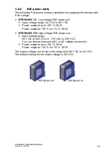
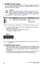
RPS90/48V LV: connecting the input voltage
With the RPS90/48V LV low-voltage PoE power unit, you connect a DC
supply voltage of 24 V DC to 48 V DC at the input connection.
The supply voltage is connected via pin 1 and pin 2.
Figure
Pin
Assignment
Voltage range
1
Minus terminal of the supply voltage
Low voltage input voltage: 24
V DC to 48 V DC
2
Plus terminal of the supply voltage
Table 7:
Connecting the low-voltage supply voltage at PoE power unit RPS90/48V
LV
2
1
Содержание Hirschmann RPS90/48V HV
Страница 66: ......


