background image

Installation MACH104-PoEP

Release 06 11/2013

25

Note: 

Read the safety guidelines under 

“Supply voltage” on page 5

.

Remove the power connector from the device.

Connect the protective conductor according to the pin assignment on the 
device with the terminal. Tighten the screws of the terminal.

Connect the lines for the supply voltage to the + and - terminals. 

Plug the terminal block into the connection for the supply voltage on the 
device.

2.4

Wiring and assembling the signal contact

Figure 4: 2-pin terminal block

 WARNING

FIRE HAZARD

Install an input fuse with a maximum rating of 10 A, characteristic B, into the 
supply line to the voltage input.
Use conductors with a minimum cross-section of 1 mm

2

 for the supply line 

to the voltage input.

Non-adherence  to  these  instructions  can  lead  to  death,  serious  
physical  injury  or  material  damage.

Figure 

Pin

Function

1

Protective grounding

2

Minus terminal of the supply voltage

3

Plus terminal of the supply voltage

Table 12: Pin assignment of the 3-pin terminal block for the supply voltage 

1 2 3

FAULT

Содержание Hirschmann MACH104-16TX-PoEP Series

Страница 1: ...Full Gigabit Family V 24 USB Aufkleber MAC Adresse P FAULT FAULT Sb RM 1 2 3 4 13 14 15 16 17 18 19 20 5 6 7 8 9 10 11 12 x y MACH104 V 24 USB Aufkleber MAC Adresse P FAULT FAULT Sb RM 1 2 3 4 13 14 15 16 17 18 19 21 22 20 5 6 7 8 9 10 11 12 x y MACH104 MACH104 16TX PoEP 2X MACH104 16TX PoEP 2X R MACH104 16TX PoEP 2X E MACH104 16TX PoEP MACH104 16TX PoEP R MACH104 16TX PoEP E ...

Страница 2: ...ures described here are binding only if they have been expressly agreed when the contract was made This document was produced by Hirschmann Automation and Control GmbH according to the best of the company s knowledge Hirschmann reserves the right to change the contents of this document without prior notice Hirschmann can give no guarantee in respect of the correctness or accuracy of the informatio...

Страница 3: ...MACH104 16TX PoEP 2X 15 1 5 2 MACH104 16TX PoEP R MACH104 16TX PoEP 2X R 15 1 5 3 MACH104 16TX PoEP E MACH104 16TX PoEP 2X E 15 1 6 Ethernet ports 15 1 6 1 10 100 1000 Mbit s twisted pair port 15 1 6 2 100 Mbit s F O port 16 1 6 3 1000 Mbit s F O port 16 1 6 4 10 Gbit s F O port 17 1 6 5 PoE ports 17 1 6 6 Combo ports 18 1 6 7 SFP XFP transceiver 18 1 7 Display elements 19 1 7 1 Device state 19 1 ...

Страница 4: ...gnal contact 25 2 5 Installing the device and grounding 26 2 5 1 Selecting the assembly location 26 2 5 2 Mounting on a flat surface 27 2 5 3 Mounting in a switch cabinet 27 2 5 4 Mounting on the wall 28 2 5 5 Grounding the device 29 2 6 Operating the device 29 2 7 Connecting network cables 30 3 Basic set up 31 3 1 Default settings 31 4 Maintenance and service 33 5 Deinstallation 34 5 1 Removing t...

Страница 5: ...ections Ensure that the connected supply voltage complies with the requirements according to IEEE 802 3af or IEEE 802 3at Use undamaged parts The device does not contain any service components Internal fuses are only triggered if there is a fault in the device If the device is not functioning correctly or if it is damaged switch off the voltage supply and return the device to the plant for inspect...

Страница 6: ...e to a concrete wall choose screws with a thread major diameter of at least 5 mm Environment Only operate the device at the specified ambient temperature temperature of the surrounding air at a distance of up to 5 cm from the device and at the specified relative humidity When you are selecting the installation location make sure you observe the climatic threshold values specified in the technical ...

Страница 7: ...y related information Any work that may be required on the electrical installation may only be carried out by personnel trained for this purpose Two or more devices configured with the same IP address can cause unpredictable operation of your network Install and maintain a process that assigns a unique IP address to every device in the network Please note that products recommended as accessories m...

Страница 8: ...f the FCC rules Operation is subject to the following two conditions 1 this device may not cause harmful interference 2 this device must accept any interference received including interference that may cause undesired operation Device variant Directive MACH104 16TX PoEP MACH104 16TX PoEP 2X MACH104 16TX PoEP R MACH104 16TX PoEP 2X R MACH104 16TX PoEP E MACH104 16TX PoEP 2X E 2011 65 EU RoHS Direct...

Страница 9: ...nment The device creates and uses high frequencies and can also radiate high frequencies and if it is not installed and used in accordance with this operating manual it can cause radio transmission interference The use of this device in a living area can also cause interference and in this case the user is obliged to cover the costs of removing the interference Recycling note After usage this devi...

Страница 10: ...y Configuration user manual Reference manual for the graphical user interface Command Line Interface user manual The Industrial HiVision Network Management Software provides you with additional options for smooth configuration and monitoring ActiveX control for SCADA integration Auto topology discovery Browser interface Client server structure Event handling Event log Simultaneous configuration of...

Страница 11: ... installation options are available 19 switch cabinet Installing the device on a flat surface Mounting on a flat surface You have the option of choosing various media to connect to the terminal devices and other network components twisted pair cable multimode F O singlemode F O The ring redundancy concept allows the network to be reconfigured quickly after a failure There are convenient options fo...

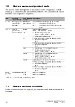
Страница 12: ...ith PoE 18 x Special properties of the device variants Blank Rated voltage range AC 100 V 240 V 50 Hz 60 Hz R Rated voltage range AC 100 V 240 V 50 Hz 60 Hz Redundant power supply E For the use of type 1 powered devices PoE Nominal voltage DC 48 V For the use of type 2 powered devices PoE Nominal voltage DC 54 V 2X Additionally 2 10 Gbit s F O ports Rated voltage range AC 100 V 240 V 50 Hz 60 Hz 2...

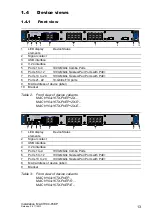
Страница 13: ...2X R MACH104 16TX PoEP 2X E 1 LED display elements Device Status 2 Signal contact 3 USB interface 4 V 24 interface 5 Ports 1 to 4 1000 Mbit s Combo Ports 6 Ports 5 to 12 1000 Mbit s Twisted Pair Ports with PoE 7 Ports 13 to 20 1000 Mbit s Twisted Pair Ports with PoE 8 MAC address of device label 9 Bracket Table 3 Front view of device variants MACH104 16TX PoEP MACH104 16TX PoEP R MACH104 16TX PoEP...

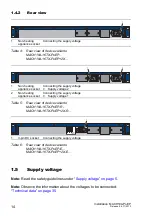
Страница 14: ...upply voltage Table 4 Rear view of device variants MACH104 16TX PoEP MACH104 16TX PoEP 2X 1 Non heating appliance socket Connecting the supply voltage Supply voltage 2 2 Non heating appliance socket Connecting the supply voltage Supply voltage 1 Table 5 Rear view of device variants MACH104 16TX PoEP R MACH104 16TX PoEP 2X R 1 3 pin DC socket Connecting the supply voltage Table 6 Rear view of devic...

Страница 15: ...kets The input voltage is electrically isolated from the housing Both inputs are separate from one another Note With non redundant supply of the mains voltage the device reports a power failure You can prevent this message by applying the supply voltage via both inputs or by changing the configuration in the Management 1 5 3 MACH104 16TX PoEP E MACH104 16TX PoEP 2X E For the supply voltage the fol...

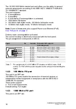
Страница 16: ...e front panel The pin assignment corresponds to MDI X 1 6 2 100 Mbit s F O port This port is an SFP slot 100 MBit s F O ports enable the connection of terminal devices or independent network segments in compliance with the IEEE 802 3 100BASE FX standard These ports support Full or half duplex mode Default setting Full duplex 1 6 3 1000 Mbit s F O port This port is an SFP slot Figure Pin Function P...

Страница 17: ...s are located in the interior of the building and are specified as SELV circuits Note You will find further information under 10 100 1000 Mbit s twisted pair port on page 15 Some twisted pair ports support Power over Ethernet PoE The PoE ports allow the connection and remote supply of for example IP telephones Voice over IP webcams sensors printer servers and WLAN access points With PoE power is s...

Страница 18: ...eivers or twisted pairs to a combo port When you are using an SFP transceiver you get an optical interface You thus deactivate the corresponding TP interface 1 6 7 SFP XFP transceiver Figure 1 SFP transceiver and XFP transceiver 1 Fast Ethernet F O SFP transceiver 2 Gigabit Ethernet F O SFP transceiver 3 10 Gigabit Ethernet F O XFP transceiver Media type Connection options Twisted pair Standard IS...

Страница 19: ...his process various LEDs light up The process takes around 15 seconds 1 7 1 Device state These LEDs provide information about conditions which affect the operation of the whole device The following table applies to the stated device variants only MACH104 16TX PoEP R MACH104 16TX PoEP 2X R The following table applies to the stated device variants only MACH104 16TX PoEP MACH104 16TX PoEP E MACH104 1...

Страница 20: ...e device detects an incorrect configuration of the HIPER Ring e g the ring is not connected to the ring port Yellow Lights up The RM function is active The redundant port is enabled RM and Sb ACA memory operation Flashing alternately Error in the memory operation flash synchronously 2 x per period Save a configuration file from the ACA to the device flash synchronously 1 x per period Saving a conf...

Страница 21: ... ACA 11 The socket housing is electrically connected to the front panel of the device The V 24 interface is not electrically isolated from the supply voltage Figure 2 Pin assignment of the V 24 interface and the DB9 connector LED Display Color Activity Meaning left LED Link status None The device detects an invalid or missing connection Green Lights up The device detects a valid connection Flashes...

Страница 22: ...ries on page 41 1 9 Signal contact The signal contact is a potential free relay contact The device allows you to perform remote diagnosis via the signal contact In the process the device signals events such as a line interruption When an event occurs the device opens the relay contact and interrupts the closed circuit The management setting specifies which events switch a contact You can also use ...

Страница 23: ...optional MACH104 16TX PoEP E MACH104 16TX PoEP 2X E Wiring and assembling the operating voltage Wiring and assembling the signal contact Installing the device and grounding Operating the device Connecting network cables Note Read the safety guidelines under Safety instructions on page 5 2 1 Unpacking and checking the content of the package Check whether the package includes all items named in sect...

Страница 24: ... SFP XFP transceiver Push the SFP XFP transceiver with the lock closed into the socket until it latches audibly in place Figure 3 F O SFP transceiver 2 3 MACH104 16TX PoEP E MACH104 16TX PoEP 2X E Wiring and assembling the operating voltage WARNING ELECTRIC SHOCK Never insert sharp objects small screwdrivers wires etc into the connection terminals for the power lines and do not touch the terminals...

Страница 25: ...on the device 2 4 Wiring and assembling the signal contact Figure 4 2 pin terminal block WARNING FIRE HAZARD Install an input fuse with a maximum rating of 10 A characteristic B into the supply line to the voltage input Use conductors with a minimum cross section of 1 mm2 for the supply line to the voltage input Non adherence to these instructions can lead to death serious physical injury or mater...

Страница 26: ...can be mounted on a flat surface in a 19 standard switch cabinet or on the wall 2 5 1 Selecting the assembly location Select the assembly location according to the safety guidelines see on page 5 Safety instructions When selecting the assembly location also make sure the following requirements are met The assembly location can be accessed for maintenance and repair work The LED display elements ar...

Страница 27: ...Install the device in the 19 switch cabinet using sliding or mounting rails This provides a more stable position of your device in environments subject to vibration For more information on sliding mounting rails and how to install them please contact your switch cabinet manufacturer The devices are designed to be mounted in a 19 switch cabinet Make sure there is sufficient ventilation If necessary...

Страница 28: ...a thread major diameter of at least 5 mm Use the pre mounted brackets included in the delivery See figure 7 on page 29 Additionally attach two brackets to the back of the device See figure 7 on page 29 P 1 LS DA 2 3 4 5 6 7 8 M4 8 TP R J45 LS DA LS DA LS DA LS DA LS DA LS DA LS DA R 1 LS DA 2 3 4 5 6 7 8 LS DA LS DA LS DA LS DA LS DA LS DA LS DA P 1 LS DA 2 3 4 5 6 7 8 1 4 7 2 5 8 3 6 M4 F AST 8SF...

Страница 29: ...e The shielding ground of the connectable industrial twisted pair lines is connected to the front panel as a conductor 2 5 5 Grounding the device The device is grounded via the power supply connections 2 6 Operating the device WARNING ELECTRIC SHOCK Solely connect a supply voltage that corresponds to the type plate of your device Failure to follow these instructions can result in death serious inj...

Страница 30: ... other You will find further information under Ethernet ports on page 15 Install the data lines according to your requirements WARNING ELECTRIC SHOCK This applies to the following device variants only MACH104 16TX PoEP E MACH104 16TX PoEP 2X E Ground the device before connecting the power supply Disconnect the grounding last Exclusively connect SELV circuits with the voltage restrictions in accord...

Страница 31: ...D 3 1 Default settings IP address The device looks for the IP address using DHCP Management password user password public read only admin password private read and write V 24 data rate 9 600 Baud Ring redundancy off Ethernet ports link status is not evaluated signal contact Optical 100 Mbit s ports 100 Mbit s full duplex All other ports autonegotiation Redundancy manager switched off DIP switch RM...

Страница 32: ...32 Installation MACH104 PoEP Release 06 11 2013 Stand by coupling switched off DIP switch RM and Stand by ON Port 3 control port port 4 coupling port for redundant ring coupling Rapid Spanning Tree on ...

Страница 33: ...relay contacts and the switching function depending on the frequency of the switching operations Hirschmann is continually working to improve and develop our software You should regularly check whether there is a new version of the software that provides you with additional benefits You will find software information and downloads on the product pages of the Hirschmann website Depending on the deg...

Страница 34: ...ckets on the device Figure 8 Disassembling the device 5 2 Deinstalling the SFP XFP transceivers Pull the SFP XFP transceiver out of the socket using the opened lock Close the SFP XFP transceiver with the protective cap Figure 9 Deinstalling an SFP transceiver V 24 USB Aufkleber MAC Adresse P FAULT FAULT Sb RM 1 2 3 4 13 14 15 16 17 18 19 20 5 6 7 8 9 10 11 12 x y MACH104 1 2 ...

Страница 35: ...ge restrictions in accordance with IEC EN 60950 1 to the supply voltage connections Ensure that the connected supply voltage complies with the requirements according to IEEE 802 3af or IEEE 802 3at For the use of type 1 powered devices PoE Nominal voltage DC 48 V Max voltage range DC 45 V 57 V For the use of type 2 powered devices PoE Nominal voltage DC 54 V Max voltage range DC 51 V 57 V Current ...

Страница 36: ...ing device variants only MACH104 16TX PoEP 2X MACH104 16TX PoEP 2X R MACH104 16TX PoEP 2X E If XFP transceivers without extension EEC are used the maximum operating temperature is reduced to 40 C For operating temperatures between 40 C and 50 C use M XFP EEC transceivers Humidity 10 95 non condensing Air pressure minimum 795 hPa 2000 m maximum 1060 hPa 1312 ft 400 m Climatic conditions during stor...

Страница 37: ...EC EN 61000 4 2 Electrostatic discharge Contact discharge Air discharge 6 kV 8 kV IEC EN 61000 4 3 Electromagnetic field 80 MHz 3000 MHz 20 V m IEC EN 61000 4 4 Fast transients burst Power line Data line 2 kV 4 kV mm inch 31 75 1 25 462 6 18 21 43 9 1 73 3 3 0 13 4 5 0 18 342 13 46 19 3 0 76 19 3 0 76 444 17 48 ...

Страница 38: ...sion EN 55022 Class A Yes FCC 47 CFR Part 15 Class A Yes TP port Length of a twisted pair segment max 100 m 328 ft for cat5e cable Table 13 TP port 10BASE T 100BASE TX 1000BASE T Product code M FAST SFP Wave length Fiber System attenuation Example for F O line length a a including 3 dB system reserve when compliance with the fiber data is observed Fiber attenuation BLP dispersion MM LC MM 1310 nm ...

Страница 39: ... data is observed 0 4 dB km 3 5 ps nm km LX LC SM 1310 nm 9 125 µm 5 20 dB 14 42 km 0 4 dB km 3 5 ps nm km LH LC LH 1550 nm 9 125 µm 5 22 dB 23 80 km 0 25 dB km 19 ps nm km LH LC LH 1550 nm 9 125 µm 15 30 dB 71 108 km 0 25 dB km 19 ps nm km LH LC LH 1550 nm 9 125 µm 15 30 dB 71 128 km 0 21 dB km typically 19 ps nm km Table 15 Fiber port 1000BASE FX SFP fiber optic Gigabit Ethernet Transceiver Prod...

Страница 40: ... 9 125 µm 5 24 dB 23 80 km 0 25 dB km 19 ps nm km Table 17 F O port bidirectional Gigabit Ethernet SFP Transceiver MACH104 PoEPdevice Order number MACH104 16TX PoEP L2P 942 030 001 MACH104 16TX PoEP R L2P 942 026 001 MACH104 16TX PoEP E L2P 942 027 001 MACH104 16TX PoEP 2X L2P 942 031 001 MACH104 16TX PoEP 2X R L2P 942 033 001 MACH104 16TX PoEP 2X E L2P 942 032 001 MACH104 16TX PoEP L3P 942 030 00...

Страница 41: ...r cord 1 Euro version CD DVD with manual Installation user manual MACH104 16TX PoEP R MACH104 16TX PoEP 2X R Device Terminal block 1 2 pin for signal contact 2 Brackets with fastening screws pre mounted Housing feet stick on Power cord 2 Euro version CD DVD with manual Installation user manual MACH104 16TX PoEP E MACH104 16TX PoEP 2X E Device Terminal block 1 2 pin for signal contact 2 Brackets wi...

Страница 42: ...3 001 M SFP LX LC EEC 942 024 001 M SFP LH LC 943 042 001 M SFP LH LC EEC 943 898 001 M SFP LH LC 943 049 001 Fast Ethernet SFP Transceiver Order number M FAST SFP TX RJ45a b a Usable with HiOS software version 03 0 and Classic Software software version 08 0 b SFP transceiver supports PRP as the redundancy protocol exclusively 942 098 001 M FAST SFP MM LC 943 865 001 M FAST SFP MM LC EEC 943 945 0...

Страница 43: ...hmann com in the product information Name EN 61000 6 2 Electromagnetic compatibility EMC Part 6 2 Generic standards Immunity for industrial environments EN 55022 Information technology equipment Radio disturbance characteristics Limits and methods of measurement FCC 47 CFR Part 15 Code of Federal Regulations EN 60950 1 Information technology equipment Safety Part 1 General requirements IEEE 802 1 ...

Страница 44: ...60 E mail inet ap belden com Hirschmann Competence Center The Hirschmann Competence Center is ahead of its competitors Consulting incorporates comprehensive technical advice from system evaluation through network planning to project planning Training offers you an introduction to the basics product briefing and user training with certification The current technology and product training courses ca...

Страница 45: ...Installation MACH104 PoEP Release 06 11 2013 45 ...

Страница 46: ...46 Installation MACH104 PoEP Release 06 11 2013 ...

Страница 47: ...Installation MACH104 PoEP Release 06 11 2013 47 ...

Страница 48: ......

Отзывы: