47
NV9601
User’s Guide
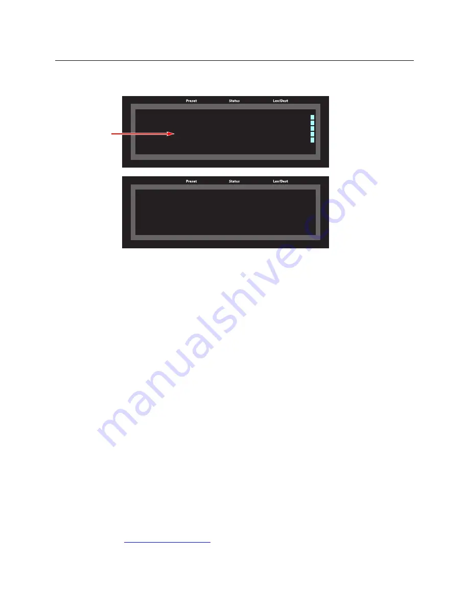
4 At this point, the level mapping is complete. The display shows a plus sign next to the
level indicating that you can view details about the level using an ‘Information’ button:
After you view the information, press the ‘Information’ button again to return to the X-Y
display.
5 Finally, press ‘Take’. After the take, the plus sign(s) migrate from the preset column to
the status column with the rest of the source data. You can view the level mapping after
the take.
You can create multiple level mappings. Level mappings are typically used for AES levels.
The level map mode is cancelled when the next normal take is performed involving the
selected devices.
Lock
This button is a toggle that sets or clears a
lock
on the current source when the panel is in
source mode or on the current destination when the panel is in destination mode.
The lock can be removed at the panel that originally set the lock, at a panel that has the
same user ID, or by a forced release at any panel.
MD Mode
In MD mode, a locked device has an “L” next to it when it appears in the display.
To lock or unlock an MD device, select the device and press a ‘Lock’ button.
X-Y Mode
In X-Y mode, you can lock or unlock the current destination on each of its levels or you can
lock a source on all levels. For destinations, select the level(s) and press the ‘Lock’ button to
perform the lock. For sources, just press the ‘Lock’ button. Select locked levels and press the
‘Lock’ button to unlock them. A locked level has an “L” next to it when it appears in the
display.
See
X Y HD
X Y HD
Dest CAM14 CAM1 SD
Dest CAM14 CAM1 SD
VTR1 CAM14 CAM1 AUDIO 1
VTR1 CAM14 CAM1 AUDIO 1
CAM14 CAM1 AUDIO 2
CAM14 CAM1 AUDIO 2
+CAM14 CAM1 AUDIO 3
+CAM14 CAM1 AUDIO 3
CAM14 CAM1 AUDIO 4
CAM14 CAM1 AUDIO 4
TIMECODE
TIMECODE
Page 1
Page 1
AUDIO 1 on CAM14 is preset to AUDIO 3 on
AUDIO 1 on CAM14 is preset to AUDIO 3 on
VTR1.
VTR1.
X-Y Display
Information Display
Mapping
marked
Содержание Grass Valley NV9000
Страница 1: ...www grassvalley com User s Guide VERSION 2 4 UG9601 04 2015 07 02 NV9601 NV9000 CONTROL PANEL...
Страница 6: ...vi Notices...
Страница 72: ...62 Operation Test...
Страница 76: ...66 Technical Details Drawings Fig 6 1 Front View of the NV9601 3 00 76 2 3 47 88 1 19 0 482 6...
Страница 78: ...68 Technical Details Drawings...


