Issue: 7
16
th
September 2015
BA627E
General Purpose
2-wire 4/20mA
manual set point
station.
For instruments with firmware 1.03
and earlier. Issued before June 2015.
Issue 7
Страница 1: ...Issue 7 16th September 2015 BA627E General Purpose 2 wire 4 20mA manual set point station For instruments with firmware 1 03 and earlier Issued before June 2015 Issue 7 ...
Страница 2: ... 5 7 Pre set outputs 5 8 Maximum output rate of change 5 9 Function of P push button in operating mode 5 10 Encoder 5 11 Security code 5 12 Reset to factory defaults 6 Maintenance 6 1 Fault finding during commissioning 6 2 Fault finding after commissioning 6 3 Servicing 6 4 Routine maintenance 6 5 Guarantee 6 6 Customer comments 7 Accessories 7 1 Scale card 7 2 Tag information 7 3 Display backligh...
Страница 3: ... current changes slowly but after the button has been pressed for five seconds the rate of change accelerates to allow large changes to be made quickly The five pre set outputs which are selectable via the instruments front panel push butons allow the operator to quickly select frequently used plant set points To prevent plant disturbance the maximum rate of output current change initiated by oper...
Страница 4: ...ng both buttons will leave the selected pre set value or Abort legend flashing for ten seconds during which time operating the E button will update the Set Point Station output to the displayed pre set value If the E button is not operated during this period the Set Point Station output will not be changed and the original engineering display will be shown While this button is pushed the Set Point...
Страница 5: ...mum voltage drop 11 3V The power supply voltage must therefore be greater than 11 3V but less than 30V which is the maximum operating voltage of the BA627E Fig 2 Typical application 4 INSTALLATION 4 1 Location The BA627E Set Point Station has a robust glass reinforced Noryl enclosure with a toughened glass window The front of the instrument has IP66 protection and a gasket seals the joint between ...
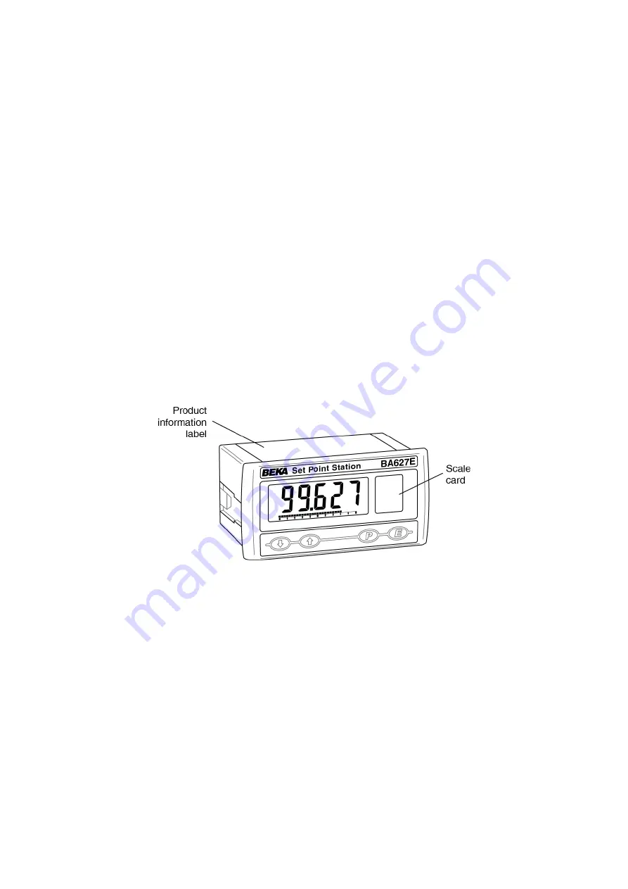
Страница 6: ... to the rear terminal block s as shown in Fig 3 To simplify installation the terminals are removable so that the panel wiring can be completed before the instrument is installed Fig 4 Fitting panel mounting clamps 4 4 Scale card The engineering units of measurement represent by the Set Point Station s 4 20mA output current may be shown on a printed scale card in a window at the right hand side of ...
Страница 7: ...lf adhesive printed scale card onto the flexible strip and insert the strip into the Set Point Station as shown below Fig 5 Inserting flexible strip carrying scale card into slot at the rear of Set Point Station 7 ...
Страница 8: ...default configuration Default Configuration Resolution rE5n 10 Display at 4mA output 2ero 0 00 Display at 20mA output 5PAn 100 00 Output current limits H L 03 000 22 000 Maximum output rate of change 000 P button in operating mode P Fn PC Pulses per rev of external encoder EnC 12 Security access code CodE 0000 Default configuration can easily be changed on site 5 1 Summary of configuration functio...
Страница 9: ...n in operating mode The Set Point Station may be configured to display the output current in milliamps the output current as a percentage or to provide access to the five pre set outputs when the P push button is pressed in the operating mode See section 5 9 EnC Encoder In addition to the Set Point Station 4 20mA output being adjusted by the front panel push buttons an external quadrature encoder ...
Страница 10: ...10 ...
Страница 11: ...t Station display to be entered The bargraph is not displayed while using the CAL function Although calibration is normally performed at 4 000mA and 20 000mA other currents may be used providing they differ by more than 4mA To calibrate the Set Point Station display select CAL from the configuration menu and press P to enter the 2Ero sub menu used for calibrating the display at the lower of the tw...
Страница 12: ...isplay the selected output current limit in milliamps with one digit flashing The flashing digit may be adjusted by pressing the or button when the flashing digit is correct pressing P will transfer control to the next digit When all the digits have been adjusted press E to return to the Lo or Hi prompt followed by E to enter the adjustments and return to the H L prompt in the configuration menu N...
Страница 13: ...mounting encoder that generates 12 contact pulses per revolution and is intended for use with the BA627E Other encoders that produce a different number of contact pulses per revolution may also be used So that all external encoders have a similar adjustment resolution the EnC function enables the number of pulses between 6 and 48 per revolution to be defined To enter the number of pulses per revol...
Страница 14: ...s LP Lo Voltage between BA627E terminal 1 3 is too low Increase 4 20mA loop supply voltage 6 2 Fault finding after commissioning ENSURE PLANT SAFETY BEFORE STARTING MAINTENANCE If a BA627E Set Point Station fails after it has been functioning correctly follow the procedure shown in section 6 1 If this does not reveal the cause of the fault it is recommended that the Set Point Station is replaced 6...
Страница 15: ... be loop or separately powered When loop powered the backlight produces background illumination enabling the display to be read at night or in poor lighting conditions No additional power supply or field wiring are required but the Set Point Station s minimum operating voltage is increased When separately powered the backlight is brighter but additional field wiring and a power supply are required...
Страница 16: ... Point Station s output current can still be controlled by the and buttons when an external encoder is connected 7 4 1 BEKA BA490 rotary encoder The BEKA BA490 quadrature output rotary encoder has been designed to operate with the BA627E Set Point Station It is an IP66 panel mounting device with a 20mm diameter control The two output waveforms and connections are shown in Fig 10 Fig 10 BA490 rotar...