Beijer Electronics 640003301 Скачать руководство пользователя страница 25

Additional Installation Tips

6.5 Safety

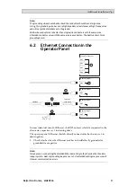
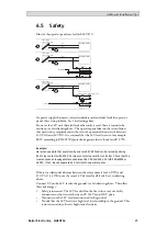
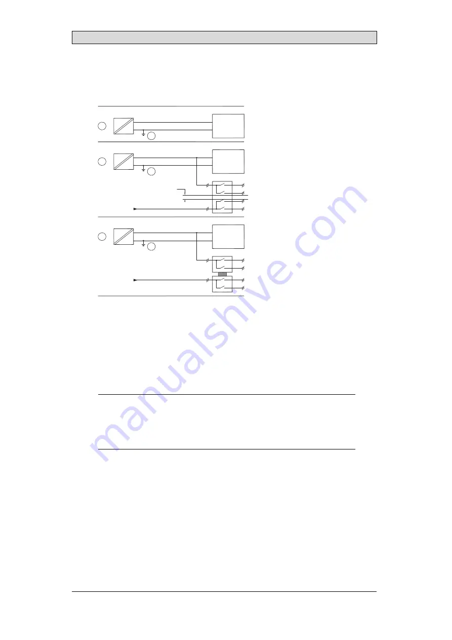
Most of the operator panels are fed with 24 V DC.

4

1

2

4

3

4

Power supply
230 V AC to 24 V DC

Power supply
230 V AC to 24 V DC

Power supply
230 V AC to 24 V DC

Operator panel

Operator panel

Operator panel

Distance?

Small controller with expansion unit

+24 V

+24 V

+24 V

0 V

0 V

0 V

230 V AC

COM1

COM100

Ch0

Ch1

Ch100

Ch101

5355

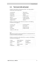
If a power supply that meets safety standards is used and only feeds the operator
panel, there is no problem. See 1 in drawing above.
However, if a 24 V unit that also feeds other units is used, there is reason to be
cautious, see 2 in drawing above. The operator panel does not have insulation
that meets safety requirements in the event of a potential short circuit between
230 V AC and 24 V DC. It is assumed that the 24 V feed is secure, for example,
SELV according to EN 60950 (protection against electric shock) and UL 950.

Example:

Here is an example that explains why a secure 24 V DC feed can be ruined by mixing
24 V relay contacts with 230 V AC relay contacts in a smaller controller. Check that the
clearances and creepage distances between 24 V DC and 230 V AC ful

fi

ll EN 60950 or

UL 950. If not, input a separate 24 V unit into the operator panel.

If there is a substantial distance between the relay contacts for 24 V DC and
230 V AC, it is OK to use the same 24 V devices for all feeds. See 3 in drawing
above.
Connect 0 V on the 24 V feed to the ground, see 4 in drawing above. This offers
three advantages:

Safety is increased. The 24 V feed will not be live in the event of a faulty
connection or short circuit between 0 V (24 V) and 230 V phase.

Transients on the 24 V feed are connected to the ground.

No risk that the 24 V feed is at a high level in relationship to the ground. This
is not unusual since there is high static electricity.

Beijer Electronics, MAEN166

25

Содержание 640003301

Страница 1: ...T15BM Installation Manual English MAEN166 2014 05...

Страница 2: ...group companies assumes no responsibility for any errors that may appear in this document Read the entire installation manual prior to installing and using this equipment Only quali ed personnel may i...

Страница 3: ...rals 11 3 TechnicalData 12 4 ChemicalResistance 14 4 1 MetalCasing 14 4 2 Touch Screen and Overlay 15 4 2 1 Auto ex EB 15 4 2 2 Touch Screen Surface 16 4 2 3 Touchscreen Protective Film 16 4 3 Termina...

Страница 4: ...he eye open ush with plenty of water and get medical attention The gures in this manualserves an illustrative purpose Because of the many variables associated with any particular installation the supp...

Страница 5: ...ow the table with cable and torque speci cationsbelow Terminal Block Connector Wire Size TQ Lb In Phoenix Contact Part No 1757022 14 20 AWG 2 08 0 52 mm2 5 7 Warning Do not open when an explosive atmo...

Страница 6: ...ccompanyinginstallation instructions Onlyquali ed personnel may install the operatorpanel Separate the high voltage signal and supply cables Make sure that the voltage and polarity of the powersource...

Страница 7: ...onment lithiumbattery electrolytic capacitorand display 1 8 Appearance of Air in Touch Screen The layerstructure of the touch screen contains airandinrare casesappearance of bubbles can arise This is...

Страница 8: ...ce Requirements Maximum installation plate thickness 8 mm Space requirements in millimeterswhen installingthe operatorpanel 100 100 100 50 50 410 286 Note The dimensions on the drawing are not proport...

Страница 9: ...rawingis available for download from the Beijer Electronics web site Formore information see sections Operator Panel Drawings and Technical Data 3 Secure the operator panel in position by screwingthe...

Страница 10: ...ignal and supply cables Shielded communication cables are recommended 24V DC RS232 RS422 RS485 24V DC A D Controller Power B Ethernet C Use 14 20 AWG 2 08 0 52 mm2 wire forthe powerconnections Connect...

Страница 11: ...chthem tostrain reliefplate with cable ties provided 2 2 3 Other Connections and Peripherals Cables peripheral equipment and accessories must be suitable forthe application and itsenvironment Forfurth...

Страница 12: ...ial port for COM1 RS232 and COM2 RS422 RS485 9 pin D sub contact with RS232 RTS CTS chassis mounted female with standard locking screws 4 40 UNC Communication module CAN Ethernet 1 x 10 100 1000 Base...

Страница 13: ...ore information 2 Standby mode The backlight is turned off there are no cabled interfaces and the CPU is below 5 Optional CAN module is present 3 Typical mode The backlight is fully powered there are...

Страница 14: ...llowing chemicals at room temperature Butanol Nitric acid 3 Hydrochloric acid 5 Nitric acid 10 Isopropyl alcohol Phosphoric acid 43 Sodium hypochlorite 10 Turpentine Note If exposure to any of the abo...

Страница 15: ...tion 1 SBP 60 95 1 Bleach 1 Hydrochloric acid 36 Sulfuric acid 10 Castor oil Linseed oil Tomato ketchup Caustic soda 40 1 Methanol Trichloroaceticacid 50 Cutting oil Nitric acid 10 White Spirit Cycloh...

Страница 16: ...ijerElectronics Solvent Resistance The chemical resistance for Auto ex EBisdescribed in section Auto exEB Outdoor Use In common with all polyesterbased lms Auto exEB is not suitable foruse in conditio...

Страница 17: ...to the following chemicalsat room temperature Acetic acid conc Na hypochlorite 10 Ammonia 30 Nitric acid 10 Butanol Phosphoric acid 10 Ethyl acetate Phosphoric acid 20 Hydrochloric acid 37 cold Note...

Страница 18: ...SB 2 USB Host 2 0 max output current 500 mA 5 Headphone Headphone Connector 6 LAN B 1 x 10 100 1000 Base T shielded RJ45 7 COM 2 RS422 RS485 Communication Port 5 2 Communication Ports Serial port 9 pi...

Страница 19: ...lDrawings 5 3 T15BM Outline 286 410 7 max 8mm 76 9 9 392 9 268 9 B C D A D A Connectors B SD memory card slot C USB host D OptionalCAN module notshown CAN depth doesnotexceed heatsink Beijer Electroni...

Страница 20: ...cordingto localelectrical codes between the operatorpanel s quick connect plinth and the panel s chassis see 2 in drawing above 2 Connect awire orgroundingbraidthat is sized correctly accordingto loca...

Страница 21: ...5 RJ45 RJ45 RJ45 Industrial Ethernet Operator panel Operator panel Operator panel Operator panel Shielded Short and unshielded 0 1 F 250 V 1 1 3 3 8 8 2 2 In some industrialunits forEthernet the RJ45...

Страница 22: ...istobreak the shield see 3 in drawing above A more elegant methodistoexpand the shielded Ethernet cablingwith a piece of unshielded Ethernetcable see 4 in drawingabove The shield canbe grounded via a...

Страница 23: ...shield to the ground via a 0 1 F 250 V plastic capacitor Both ends are then connected tothe ground in terms ofHF but only connected to the ground at one end in terms ofLF thus avoidingthe 50 60 Hz gro...

Страница 24: ...to heat The lifespan of an electrolytic capacitoris cut in halfwith an 8 10 C increase in temperature A 15 20 C temperature increase resultsin a quarter of the lifespanetc Rittal has a goodprogram for...

Страница 25: ...Vaccording to EN 60950 protection against electric shock andUL 950 Example Here is an example that explains why a secure 24 V DC feed can be ruined by mixing 24 V relay contacts with 230 V AC relay co...

Страница 26: ...al Many peripherals includingUSBdevices will bond the terminal s signal ground 0 V to the protective earth ground Bonding signal ground and protective earth ground mayincrease electricalemissions and...

Страница 27: ...the ground potential the shield should be connected tothe ground via 0 1 F 250 V plastic capacitorto preventground current in the braided shield A numberof manufacturers recommendthat the shield be g...

Отзывы: