background image

Foreword

KL3403

9

Version: 3.1.0

Firmware (FW) and hardware versions (HW)

Documen-
tation,
Version

KL3403-0000

KL3403-0010

KL3403-0014

KL3403-0020

KL3403-0022

KL3403-0025,
KL3403-0026

KL3403-0333

FW

HW

FW

HW

FW

HW

FW

HW

FW

HW

FW

HW

FW

HW

3.1.0

3L

17

3L

17

4K

17

4K

17

4K

15

3L

17

4K

17

3.0.0

3L

17

3L

17

4K

17

4K

17

4K

15

3L

17

-

-

2.1.0

3L

15

3L

15

4K

16

4K

15

4K

15

3L

15

2.0.1

3L

15

3L

15

4K

15

4K

15

4K

15

3L

15

2.0.0

3K

15

3K

15

4J

15

4J

15

4J

15

3K

15

1.9.0

3K

15

3K

15

4J

15

4J

15

4J

15

3K

15

1.8.0

3K

15

3K

15

4J

15

4J

15

4J

15

3K

15

1.7.0

3J

15

3J

14

4i

15

4i

15

4i

15

3J

15

1.6.0

3H

10

3H

10

3H

10

4G

10

3H

10

3H

10

1.5.0

3G

10

3G

10

-

-

4F

10

4F

10

3G

10

1.4.1

3F

10

3F

10

4E

10

-

-

-

-

1.4

3E

10

3E

10

4D

10

1.3

3E

10

3E

04

-

-

1.2

3D

09

3D

03

1.1

3B

06

3B

00

1.0

2E

03

-

-

The firmware and hardware versions (delivery state) can be taken from the serial number printed on the side
of the terminal.
The current firmware version is also displayed by the 

KS2000 [

}

 41]

 configuration software.

Syntax of the serial number

Structure of the serial number: WW YY FF HH

WW - week of production (calendar week)
YY - year
FF - firmware version
HH - hardware version

Example with ser. No.: 35 04 2E 03:

35 - week of production 35
04 - year of production 2004
2E - firmware version 2E
03 - hardware version 03

1.4

Beckhoff Identification Code (BIC)

The Beckhoff Identification Code (BIC) is increasingly being applied to Beckhoff products to uniquely identify
the product. The BIC is represented as a Data Matrix Code (DMC, code scheme ECC200), the content is
based on the ANSI standard MH10.8.2-2016.

Содержание KL3403 Series

Страница 1: ...Documentation KL3403 3 Phase Power Measurement Terminals 3 1 0 2019 09 20 Version Date...

Страница 2: ......

Страница 3: ...pplication example for DC 33 3 4 3 Application example with frequency converter 34 3 4 4 Application example for KL3403 0014 36 4 KS2000 Configuration Software 38 4 1 KS2000 Introduction 38 4 2 Parame...

Страница 4: ...Table of contents KL3403 4 Version 3 1 0...

Страница 5: ...tion of products that have already been supplied may be made on the basis of the data diagrams and descriptions in this documentation Trademarks Beckhoff TwinCAT EtherCAT EtherCAT G EtherCAT G10 Ether...

Страница 6: ...ained specialists in control automation and drive engineering who are familiar with the applicable national standards Description of instructions In this documentation the following instructions are u...

Страница 7: ...KS2000 Configuration software Description of KL3403 0333 added KL3403 0021 deleted Technical data updated Chapter Instructions for ESD protection added 3 0 0 Migration 2 1 0 Register description upda...

Страница 8: ...erminal version corrected 1 2 Description of control and status bytes extended Process data index for frequency measurement amended Description of the KL3403 parameterization with the KS2000 software...

Страница 9: ...10 4E 10 1 4 3E 10 3E 10 4D 10 1 3 3E 10 3E 04 1 2 3D 09 3D 03 1 1 3B 06 3B 00 1 0 2E 03 The firmware and hardware versions delivery state can be taken from the serial number printed on the side of th...

Страница 10: ...according to the table below If the information is shorter spaces are added to it The data under positions 1 to 4 are always available The following information is contained Item no Type of informatio...

Страница 11: ...cters that will replace all other serial number systems at Beckhoff in the long term e g batch designations on IO components previous serial number range for safety products etc The BTN will also be i...

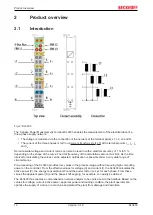
Страница 12: ...As the time interval for calculating the values can be adjusted optimization is possible under a very wide range of circumstances Pre processing of the KL3403 provides rms values in the process image...

Страница 13: ...e sensitive current circuits 20 mA KL3403 0022 Power measurement terminal with 6 current circuits otherwise like KL3403 0020 20 mA KL3403 0025 Power measurement terminal with more sensitive current ci...

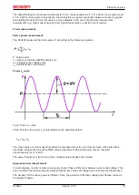
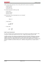
Страница 14: ...u and current i curves Fig 4 Voltage u and current i curves RMS value calculation The rms value for voltage and current is calculated over a measuring interval in this case the period T The following...

Страница 15: ...voltage value i t instantaneous current value Power s t curve Fig 5 Power s t curve In the first step the power s t is calculated at each sampling instant The mean value over the measuring interval is...

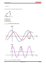
Страница 16: ...6 Version 3 1 0 The active power is smaller than the apparent power S Apparent power P Active power Q Reactive power Phase shift angle u t i t p t curves with phase shift angle Fig 6 u t i t p t curve...

Страница 17: ...provide about information the direction of the energy flow A positive sign indicates the motor mode a negative sign indicates generator mode In addition the sign of the reactive power Q indicates the...

Страница 18: ...instantaneous value and the peak rms value The peak rms value always refers to the peak value within the specified measuring interval Frequency measurement The KL3403 can measure the frequency of the...

Страница 19: ...3 0 3 1 0 3 0 3 0 5 0 5 0 5 Power calcu lated 1 0 4 0 3 1 5 4 0 3 1 0 1 0 Measuring procedure True RMS with 64000 samples s Measuring cycle time freely configurable 50 ms per measured value pre set D...

Страница 20: ...h an interface for 20 mA Overcurrent limiting factor FS The overcurrent limiting factor FS of a current transformer indicates at what multiple of its primary rated current the current transformer chan...

Страница 21: ...e measured on the side of the current measurement using a multimeter with an internal resistance of 10 M which does not represent an insulation fault Additional measuring instruments in the current ci...

Страница 22: ...with highly insulating materials synthetic fibers plastic film etc Surroundings working place packaging and personnel should by grounded probably when handling with the devices Each assembly must be t...

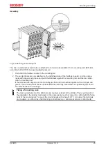
Страница 23: ...lock clicks onto the mounting rail If the terminals are clipped onto the mounting rail first and then pushed together without tongue and groove the connection will not be operational When correctly a...

Страница 24: ...nents The six spring contacts of the K Bus E Bus deal with the transfer of the data and the supply of the Bus Terminal electronics The power contacts deal with the supply for the field electronics and...

Страница 25: ...mm from the group of terminals WARNING Risk of electric shock The PE power contact must not be used for other potentials 3 3 Connection 3 3 1 Connection system WARNING Risk of electric shock and dama...

Страница 26: ...nates the risk of wires being mixed up The familiar dimensions of the terminal only had to be changed slightly The new connector adds about 3 mm The maximum height of the terminal remains unchanged A...

Страница 27: ...sassembly or wiring of the Bus Terminals Terminals for standard wiring ELxxxx KLxxxx and for pluggable wiring ESxxxx KSxxxx Fig 15 Connecting a cable on a terminal point Up to eight terminal points en...

Страница 28: ...HD Terminals are connected without tools for single wire conductors using the direct plug in technique i e after stripping the wire is simply plugged into the terminal point The cables are released as...

Страница 29: ...e mounting rail IL1 5 Current transformer at L1 Connections for the current transformers See note 30 under Operate the current transformer as in tended IL2 6 Current transformer at L2 IL3 7 Current tr...

Страница 30: ...off I O system only examined for risk of fire or electric shock in accordance with UL508 and CSA C22 2 No 142 Phase voltage according to UL specifications 300 V max The maximum phase voltage of 500 V...

Страница 31: ...e KL3403 to the secondary windings of the current transformers before using the current transformer Power measurement at a machine The voltage is measured via connections L1 L2 L3 and N The current is...

Страница 32: ...y Current measurement on a motor CAUTION Make sure terminal point N is zeroed or grounded If you do not connect the terminal point N with the neutral conductor of your mains supply e g if the KL3403 i...

Страница 33: ...communication register R32 4 54 for measuring direct voltage and DC Power measurement at a fieldbus station The example illustrates power measurement at three circuits of the fieldbus station The ter...

Страница 34: ...injury through electric shock and damage to the device Bring the Bus Terminals system into a safe de energized state before starting mounting disassembly or wiring of the Bus Terminals The example il...

Страница 35: ...y distortions caused by the three phase transformer have little effect on the practical measurement during the transfer of the harmonics created by the frequency converter The power distribution is ma...

Страница 36: ...the external shunts to terminal points UI1 UI2 and UI3 of the KL3403 0014 Fig 21 Application example for KL3403 0014 The example shows a power measurement for three incandescent lamps Three external s...

Страница 37: ...the shunts A voltage drop of 60 mV x A is typically indicated for the shunts Examples Nominal value of the shunt 60 mV 1 A 60 mV 25 A 60 mV 100 A Sample current 1 A 25 A 100 A Current output value of...

Страница 38: ...s Box Modules can be prepared before the commissioning phase Later on this configuration can be transferred to the terminal station in the commissioning phase by means of a download For documentation...

Страница 39: ...r s input and output images can be observed by monitoring Process values can be specified in the output image for commissioning of the output modules All possibilities in the online mode can be used i...

Страница 40: ...e terminals of the fieldbus station in a tree structure The right hand KS2000 window contains a graphic display of the fieldbus station terminals In the tree structure of the left hand window click on...

Страница 41: ...he KL3403 can be found under Settings 41 ProcData shows the process data of the KL3403 4 3 Settings The dialog mask for the parameterization of the KL3403 can be found under Settings Fig 25 Settings v...

Страница 42: ...ange the scaling of the energy consumption measurement Default 4dec KL3403 0000 002x 0333 0 01 kWh KL3403 0010 0 05 kWh Minimum input voltage undervoltage threshold R36 54 Here you can change the unde...

Страница 43: ...leted the value cannot be restored 4 4 Sample program for KL register communication via EtherCAT on KL3314 exemplary Using the sample programs This document contains sample applications of our product...

Страница 44: ...coupler e g BK1120 or embedded PC KL3314 KL9010 Download https infosys beckhoff com content 1033 kl3403 Resources zip 5996114571 zip Preparations for starting the sample programs tnzip file TwinCAT 3...

Страница 45: ...figuration of the example Checking NetId the EtherCAT tab of the EtherCAT device shows the configured NetId The first 4 numbers have to be identical with the project NetId of the target system The pro...

Страница 46: ...l byte 3 CB3 49 7 10 Word DataIN3 DataOUT3 Word alignment The Bus Coupler places values on even byte addresses No compact process image The KL3403 cannot be operated with compact process image without...

Страница 47: ...read with input data word 1 DataIN1 46 The following process data indices are supported Index Symbol Measured value Resolution 0000bin 0x0 Irms Current 14 rms value 0 001 A KL3403 0000 KL3403 0026 0 0...

Страница 48: ...ored in an EEPROM The EEPROM manufacturer specifies a mini mum of 100000 typically 1 million possible write operations for this function block The resulting service life of the energy consumption memo...

Страница 49: ...e Description SB1 7 RegAccess 1bin Acknowledgment for register access SB1 6 R 0bin Read access SB1 5 to SB1 0 Reg no Number of the register that was read or written Control and status byte of the seco...

Страница 50: ...ltage RMS value of phase L1 reading the active power of phase L2 and reading the power factor of phase L3 Enter process data index 0x1 in control byte 1 The voltage rms value of phase L1 is returned i...

Страница 51: ...Password change register R6 Diagnostic register R RAM R7 52 Command register R8 53 Terminal type 0x0D4B 3403dec R ROM R9 53 Firmware version e g 0x3143 12611dec R ROM R10 Multiplex shift register 0x02...

Страница 52: ...he terminal R7 Command register Command 0x1004 Deleting the energy consumption user password must be set Write the value 0x1004 into the command register in order to delete the energy consumption stor...

Страница 53: ...c R37 54 1 R38 55 200dec R39 55 50dec Repeating the new password Repeat the new password in the command register when you change the password see password change register description R5 52 R8 Terminal...

Страница 54: ...0 enUserScaling 0bin User scaling is switched off ratio is 1 1 0bin 1bin User scaling is switched on ratio is 1 R37 0bin KL3403 0000 KL3403 0010 KL3403 0025 KL3403 0026 KL3403 0333 1bin KL3403 0020 K...

Страница 55: ...frequency among other factors see chapter Basic function principles 14 5 6 Examples of Register Communication The numbering of the bytes in the examples corresponds to the display without word alignm...

Страница 56: ...ter number 31 with 01 1111bin The output data word byte 1 and byte 2 contains the code word 0x1235 for deactivating write protection Input Data answer of the bus terminal Byte 0 Status byte Byte 1 Dat...

Страница 57: ...efer to the description of the feature register of your terminal chapter Register description regarding the meaning of the individual bits before changing the values Input data response from the Bus T...

Страница 58: ...egister communication switched on Bit 0 6 set means writing to the register Bits 0 5 to 0 0 specify the register number 31 with 01 1111bin The output data word byte 1 and byte 2 contains 0x0000 for re...

Страница 59: ...nected to the neutral conductor Check the wiring They want to measure DC but the KL3403 does not show any meaningful values The DC filter of the KL3403 are switched on delivery state Switch off the DC...

Страница 60: ...e additional current circuits instead of the voltage circuits also 20 mA Current and sampling curve for input signals within the permitted measuring range If the current input values are within the pe...

Страница 61: ...ubject to an ever greater measuring error due to the input overload Fig 31 Current and sampling curve for 50 overload In the example shown the terminal outputs a value of approx 1250dec for the RMS va...

Страница 62: ...n 3 1 0 Fig 32 Increase in measuring error with increasing overload The output values indicated for input overloads of 20 and 50 are typical values They may differ to some degree due to component tole...

Страница 63: ...ment Measurements of small DC voltages may be subject to small measuring inaccuracies since the voltage inputs are subject to a small non linearity Fig 33 Measuring error for DC voltage measurement Th...

Страница 64: ...f components there Beckhoff Headquarters Beckhoff Automation GmbH Co KG Huelshorstweg 20 33415 Verl Germany Phone 49 5246 963 0 Fax 49 5246 963 198 e mail info beckhoff com Beckhoff Support Support of...

Страница 65: ...at a machine 31 Fig 18 Application example current measurement at a motor 32 Fig 19 Application example power measurement at a fieldbus station 34 Fig 20 Application example with frequency converter 3...

Отзывы: