


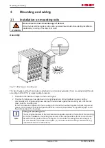


Mounting and wiring
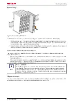
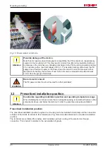
Fig. 13: Power contact on left side
Attention
Possible damage of the device
Note that, for reasons of electromagnetic compatibility, the PE contacts are capacitatively
coupled to the mounting rail. This may lead to incorrect results during insulation testing or
to damage on the terminal (e.g. disruptive discharge to the PE line during insulation testing
of a consumer with a nominal voltage of 230 V). For insulation testing, disconnect the PE
supply line at the Bus Coupler or the Power Feed Terminal! In order to decouple further
feed points for testing, these Power Feed Terminals can be released and pulled at least
10 mm from the group of terminals.
WARNING
Risk of electric shock!
The PE power contact must not be used for other potentials!
3.2
Prescribed installation position
Attention
Constraints regarding installation position and operating temperature range
When installing the terminals ensure that an adequate spacing is maintained between other
components above and below the terminal in order to guarantee adequate ventilation!
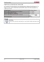
Prescribed installation position
The prescribed installation position requires the mounting rail to be installed horizontally and the connection
surfaces of the EL/KL terminals to face forward (see Fig.
Recommended distances for standard installation
position
).
The terminals are ventilated from below, which enables optimum cooling of the electronics through
convection. "From below" is relative to the acceleration of gravity.
KL2535, KL2545
20
Version: 2.0.0
Содержание KL2535
Страница 1: ...Documentation KL2535 KL2545 Pulse width current terminals 2 0 0 2016 02 29 Version Date...
Страница 2: ......