background image

EtherCAT Box - Introduction

EP9300-0022

9

Version: 2.3

2

EtherCAT Box - Introduction

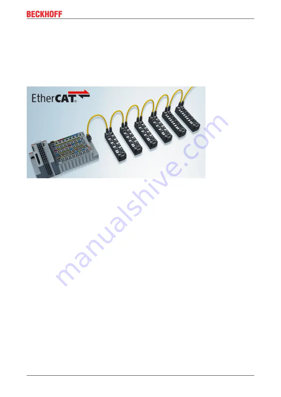
The EtherCAT system has been extended with EtherCAT Box modules with protection class IP67. Through
the integrated EtherCAT interface the modules can be connected directly to an EtherCAT network without an
additional Coupler Box. The high-performance of EtherCAT is thus maintained into each module.

The extremely low dimensions of only 126 x 30 x 26.5 mm (h x w x d) are identical to those of the Fieldbus
Box extension modules. They are thus particularly suitable for use where space is at a premium. The small
mass of the EtherCAT modules facilitates applications with mobile I/O interface (e.g. on a robot arm). The
EtherCAT connection is established via screened M8 connectors.

Fig. 1: EtherCAT Box Modules within an EtherCAT network

The robust design of the EtherCAT Box modules enables them to be used directly at the machine. Control
cabinets and terminal boxes are now no longer required. The modules are fully sealed and therefore ideally
prepared for wet, dirty or dusty conditions.

Pre-assembled cables significantly simplify EtherCAT and signal wiring. Very few wiring errors are made, so
that commissioning is optimized. In addition to pre-assembled EtherCAT, power and sensor cables, field-
configurable connectors and cables are available for maximum flexibility. Depending on the application, the
sensors and actuators are connected through M8 or M12 connectors.

The EtherCAT modules cover the typical range of requirements for I/O signals with protection class IP67:

• digital inputs with different filters (3.0 ms or 10 μs)

• digital outputs with 0.5 or 2 A output current

• analog inputs and outputs with 16 bit resolution

• Thermocouple and RTD inputs

• Stepper motor modules

XFC (eXtreme Fast Control Technology) modules, including inputs with time stamp, are also available.

Содержание EP9300-0022

Страница 1: ...Documentation EN EP9300 0022 PROFINET RT EtherCAT Box 2022 03 31 Version 2 3...

Страница 2: ......

Страница 3: ...ons 16 4 2 1 Connector overview 16 4 2 2 Profinet 17 4 2 3 EtherCAT output 19 4 2 4 Supply voltages 21 4 2 5 Diag port 23 4 3 UL Requirements 24 4 4 Disposal 25 5 Commissioning and configuration 26 5...

Страница 4: ...itions 57 9 2 Accessories 58 9 3 Version identification of EtherCAT devices 59 9 3 1 General notes on marking 59 9 3 2 Version identification of EP EPI EPP ER ERI boxes 60 9 3 3 Beckhoff Identificatio...

Страница 5: ...products that have already been supplied may be made on the basis of the data diagrams and descriptions in this documentation Trademarks Beckhoff TwinCAT TwinCAT BSD TC BSD EtherCAT EtherCAT G EtherCA...

Страница 6: ...trained specialists in control automation and drive engineering who are familiar with the applicable national standards Description of instructions In this documentation the following instructions are...

Страница 7: ...ped further Modules having earlier production statuses cannot have the same properties as modules with the latest status However existing properties are retained and are not changed so that older modu...

Страница 8: ...ks The latter should be connected to the corporate network or the Internet only if appropriate protective measures have been set up In addition the recommendations from Beckhoff regarding appropriate...

Страница 9: ...design of the EtherCAT Box modules enables them to be used directly at the machine Control cabinets and terminal boxes are now no longer required The modules are fully sealed and therefore ideally pre...

Страница 10: ...ensors actuators Fig 3 EtherCAT Box with M12 connections for sensors actuators Basic EtherCAT documentation You will find a detailed description of the EtherCAT system in the Basic System Documentatio...

Страница 11: ...ROFINET RT to EtherCAT One station consists of an EP9300 0022 and any number of EtherCAT Box modules The box is connected to PROFINET RT via a D coded M12 socket With EtherCAT the PROFINET RT box can...

Страница 12: ...n M8 socket 4 pin black US nominal voltage 24 VDC 15 20 US sum current IS sum max 4 A Current consumption from US 120 mA Rated voltage UP 24 VDC 15 20 UP sum current IP sum max 4 A Current consumption...

Страница 13: ...start up No MRP Yes SNMP Yes LLDP Yes ARP Yes LLDP Yes DHCP Yes 3 3 Scope of supply Make sure that the following components are included in the scope of delivery 1x EP9300 0022 1x protective cap for E...

Страница 14: ...wing is not true to scale Housing features Housing material PA6 polyamide Sealing compound polyurethane Mounting two fastening holes 4 5 mm for M4 Metal parts brass nickel plated Contacts CuZn gold pl...

Страница 15: ...plug connectors against dirt during the assembly Mount the module with two M4 screws in the centrally located fastening holes 4 1 3 Functional earth FE The Fixing 15 also serve as connections for the...

Страница 16: ...60 Supply voltage input 21 M8 plug connector 0 4 Nm 1 X61 Supply voltage downstream connection 21 M8 socket 0 4 Nm 1 X101 EtherCAT output 19 M8 0 4 Nm 1 X201 Diag port 23 1 Mount plugs on these connec...

Страница 17: ...2 2 1 Connector 1 2 3 4 Fig 6 M12 socket D coded Pin Core color 1 Signal 1 Yellow Tx 2 White Rx 3 orange Tx 4 blue Rx Housing Shield 1 The core colors apply to EtherNet EtherCAT cables with M12 conne...

Страница 18: ...of switches without LLDP Profinet uses the LLDP protocol for the topology recognition The topology recognition and the as sociated Profinet services will not work properly if the switch that you use...

Страница 19: ...32 ZK1090 6292 ZK1090 3xxx xxxx ZB9031 and old ver sions of ZB9030 ZB9032 ZK1090 3xxx xxxx TIA 568B Tx Pin 1 Pin 1 Pin 1 yellow2 orange white3 white orange Tx Pin 4 Pin 3 Pin 2 orange2 orange3 orange...

Страница 20: ...thernet cables that meet the requirements of at least category 5 CAT5 according to EN 50173 or ISO IEC 11801 should be used EtherCAT uses four wires for signal transmission Thanks to automatic line de...

Страница 21: ...attention also for the redirection of the supply voltages US and UP the maximum permissible current for M8 connectors of 4 A must not be exceeded 4 2 4 1 Connectors NOTE Risk of confusion supply volt...

Страница 22: ...below the minimum nominal voltage Variations in the voltage of the power supply unit must also be taken into account Voltage drop on the supply line Vert Faktor 0 45 cm V 5 10 15 20 2 4 6 8 10 25 0 0...

Страница 23: ...Mounting and connection EP9300 0022 23 Version 2 3 4 2 5 Diag port The Diag port is used to update the firmware of the EP9300 0022 Update the firmware only in consultation with Beckhoff Support 65...

Страница 24: ...4 Amp or by a 24 VDC power source that has to satisfy NEC class 2 A NEC class 2 power supply shall not be connected in series or parallel with another class 2 power source CAUTION CAUTION To meet the...

Страница 25: ...ucts marked with a crossed out wheeled bin shall not be discarded with the normal waste stream The device is considered as waste electrical and electronic equipment The national regulations for the di...

Страница 26: ...should assign the IP address Fig 13 Rotary switch S1 S1 Source of the IP address 1 DHCP server 3 Profinet controller 5 2 Profinet name The Profinet name of the EP9300 0022 is EP9300 xxx xxx is a deci...

Страница 27: ...0022 is operated as a PTP Slave or an IRT device and is synchronous Bit 1 IsPTPMaster is set when the EP9300 0022 is operated as a PTP Master Bit 2 ECFrameError is set when a problem is determined at...

Страница 28: ...according to their process data This option can be used with 2 or 4 channel terminals To do this a 2 or 4 channel pack terminal without asterisk must be appended to the GSDML file In order to fill th...

Страница 29: ...tion data GSDML Note that the complete maximum data length of the EL6631 0010 cannot be used The length is dependent on the other EtherCAT devices attached to the EP9300 EL6731 0010 The PROFIBUS slave...

Страница 30: ...to plug in or unplug devices during the runtime a further Sync Unit must be configured This is not possible with EP9300 0022 In this case use a CX8093 EtherCAT devices that don t exist in the GSDML So...

Страница 31: ...3 Fig 18 Sample configuration with EK1122 2 port EtherCAT junction If both junctions are not used then junction 1 and 2 are short circuited as it were and the EtherCAT frame continues directly from th...

Страница 32: ...were and the EC frame continues directly from the terminal to the right Note that in the PROFINET controller the modules are entered in the direction of the EtherCAT frame Connection during operation...

Страница 33: ...minal itself i e the generally valid diagnosis for the terminal is operated via this The actual process data are plugged into sub slot 2 and the PDO mapping on the EC master is generated on their basi...

Страница 34: ...during operation Commissioning EL7031 The default settings are adequate for initial commissioning i e only the corresponding sub module needs to be selected The PDOs and SDOs of the terminal are param...

Страница 35: ...carry out optimizations during operation Solution The CoE data are sent via acyclic PROFINET services PROFINET index 0x200F The position of the EtherCAT device is specified via the slot number The Co...

Страница 36: ...ngth of the following data Data Write Byte 1 1 Byte 2 0 Byte 3 0 Byte 4 0 Response Bytes 1 4 ADS error Bytes 4 x COE data value CoE data The response to the Read Request i e the Read Response includes...

Страница 37: ...e error code 0 indicates error free response The error code is an ADS error code Further information can be found under the following link http infosys beckhoff com content 1031 tcsample html ads_retu...

Страница 38: ...ls are included in the maximum project configuration they can be disabled by the controller so that the hardware and the parameterized configuration match again As soon as this is done EP9300 0022 swi...

Страница 39: ...als at runtime is a feature of the PROFINET controller and may or may not be possible in practice depending on the manufacturer of the PROFINET controller Option 2 The configuration is sent by the PLC...

Страница 40: ...cannot be used for the multi configuration mode Only slots can be used irrespective of a module using subslots or not No Shared Device The Shared Device feature cannot be used when the multi configura...

Страница 41: ...ule used by the IO Link master is a diagnostics module This is always present when the EL6224 EP6224 is added This submodule contains the status of all connected IO Link devices If the sensor is in IO...

Страница 42: ...ufacturers please use a generic channel and select the process data size Configuration of the IO Link device The minimum settings required for operating an IO Link device are IO Link version Generally...

Страница 43: ...be read or written The EK9300 does not support this function I e no parameters can be read or written The communication of the EK9300 with the IO Link device is limited to the process data To access...

Страница 44: ...vated again via the record data see below Activation of EtherCAT following an EtherCAT error Information about the EtherCAT state can be obtained in the DAP via the DWord Status As soon as an error is...

Страница 45: ...cess the web page the following requirements must be met The web page must be enabled via the parameter data of the EP9300 0022 The PROFINET controller must have exchanged data with the EP9300 0022 at...

Страница 46: ...embly of the devices Disposal In order to dispose of the device it must be removed In accordance with the WEEE Directive 2012 19 EU Beckhoff takes back old devices and accessories in Germany for prope...

Страница 47: ...xchange of data between controllers and field devices in several real time classes RT software based real time and IRT hardware supported isochronous real time In addition further Ethernet traffic can...

Страница 48: ...Bus Coupler BK9053 PROFINET Compact Bus Coupler for Bus Terminals BK9103 PROFINET Bus Coupler for Bus Terminals EK9300 PROFINET Bus Coupler for EtherCAT Terminals EtherCAT Box EP9300 PROFINET Coupler...

Страница 49: ...tocol as with ModbusTCP or EtherNet IP 1 Except for e g the EK1100 coupler which has neither process data nor configuration data it is equipped with an EtherCAT ASIC and is therefore also visible in t...

Страница 50: ...display the process data in more detail although they are described in the GSDML 3 Display which PDOs are active in the process data 4 View of all PDOs 5 Detailed single PDOs which can be selected in...

Страница 51: ...5 Status_Error BIT BOOL 0 6 Status_Sync error BIT BOOL 1 5 Status_TxPDO State BIT BOOL 1 6 Status_TxPDO Toggle BIT BOOL 1 7 AI Standard Channel 1 Value 16 BIT INT 2 0 3 7 AI Standard Channel 2 BitArra...

Страница 52: ...in the GSDML Beckhoff uses the same names and meanings here as on the EtherCAT side which is contained in the ESI file2 in the CoE description Fig 31 EtherCAT Parameter data of the EL3162 of the ESI u...

Страница 53: ...ind these parameters for the individual terminals in the configuration tool of your PROFINET controller regardless of which vendor you use here You can also access individual parameters acyclically vi...

Страница 54: ...ile The GSDML file can be found at www beckhoff com Where can I find the MAC address of EP9300 0022 The MAC address is printed on the box What is the Diag port interface for and what can I do with it...

Страница 55: ...is ready red illuminated May only light up during the start up phase PN red flashing 200 ms Start up phase green flashing 200 ms No Profinet name 26 green flashing 1 s off 200 ms on No IP address 26...

Страница 56: ...nection to the next Profinet module green flashing Activity communication with the next Profinet module Supply voltage status LED Display Meaning Us 24 V off The power supply voltage Us is not present...

Страница 57: ...tection Definition 0 Non protected 1 Protected against water drops 2 Protected against water drops when enclosure tilted up to 15 3 Protected against spraying water Water sprayed at an angle up to 60...

Страница 58: ...tion ZS5000 0010 Protective cap for M8 sockets IP67 50 pieces ZS5000 0020 Protective cap for M12 sockets IP67 50 pcs ZS5100 0000 Inscription labels unprinted 4 strips of 10 ZS5000 xxxx Printed inscrip...

Страница 59: ...ntifier in the case of 0000 usually abbreviated to EL3314 0016 is the EtherCAT revision The order identifier is made up of family key EL EP CU ES KL CX etc type 3314 version 0000 The revision 0016 sho...

Страница 60: ...06 production year 2006 3A firmware version 3A 02 hardware version 02 Exceptions can occur in the IP67 area where the following syntax can be used see respective device documentation Syntax D ww yy x...

Страница 61: ...t it can be found in the following places on the packaging unit directly on the product if space suffices on the packaging unit and the product The BIC is machine readable and contains information tha...

Страница 62: ...of composite information from positions 1 to 4 and with the above given example value on position 6 The data identifiers are highlighted in bold font 1P072222SBTNk4p562d71KEL1809 Q1 51S678294 Accordi...

Страница 63: ...introduced into the Beckhoff I O production terminals boxes from 2020 widespread implementation is expected in 2021 The user can electronically access the eBIC if existent as follows With all EtherCAT...

Страница 64: ...pecific content is stored with the help of a category according to ETG 2010 ID 03 indicates to all EtherCAT masters that they must not overwrite these data in case of an update or restore the data aft...

Страница 65: ...there Beckhoff Support Support offers you comprehensive technical assistance helping you not only with the application of individual Beckhoff products but also with other wide ranging services suppor...

Страница 66: ......

Страница 67: ...Beckhoff Automation GmbH Co KG H lshorstweg 20 33415 Verl Germany Phone 49 5246 9630 info beckhoff com www beckhoff com More Information www beckhoff com ep9300 0022...

Отзывы: