Mounting and wiring
EL33xx-00x0
73
Version: 4.2
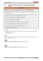
4.16
ATEX - Special conditions (extended temperature
range)
WARNING
Observe the special conditions for the intended use of Beckhoff fieldbus components with
extended temperature range (ET) in potentially explosive areas (directive 94/9/EU)!
• The certified components are to be installed in a suitable housing that guarantees a protection class of at
least IP54 in accordance with EN 60529! The environmental conditions during use are thereby to be
taken into account!
• If the temperatures during rated operation are higher than 70°C at the feed-in points of cables, lines or
pipes, or higher than 80°C at the wire branching points, then cables must be selected whose tempera-
ture data correspond to the actual measured temperature values!
• Observe the permissible ambient temperature range of -25 to 60°C for the use of Beckhoff fieldbus com-
ponents with extended temperature range (ET) in potentially explosive areas!
• Measures must be taken to protect against the rated operating voltage being exceeded by more than
40% due to short-term interference voltages!
• The individual terminals may only be unplugged or removed from the Bus Terminal system if the supply
voltage has been switched off or if a non-explosive atmosphere is ensured!
• The connections of the certified components may only be connected or disconnected if the supply volt-
age has been switched off or if a non-explosive atmosphere is ensured!
• The fuses of the KL92xx/EL92xx power feed terminals may only be exchanged if the supply voltage has
been switched off or if a non-explosive atmosphere is ensured!
• Address selectors and ID switches may only be adjusted if the supply voltage has been switched off or if
a non-explosive atmosphere is ensured!
Standards
The fundamental health and safety requirements are fulfilled by compliance with the following standards:
• EN 60079-0:2012+A11:2013
• EN 60079-15:2010
Marking
The Beckhoff fieldbus components with extended temperature range (ET) certified for potentially explosive
areas bear the following marking:
II 3G KEMA 10ATEX0075 X Ex nA IIC T4 Gc Ta: -25 … 60°C
or
II 3G KEMA 10ATEX0075 X Ex nC IIC T4 Gc Ta: -25 … 60°C
Содержание EL33-00 Series
Страница 2: ......
Страница 6: ...Table of contents EL33xx 00x0 6 Version 4 2...
Страница 17: ...Product overview EL33xx 00x0 17 Version 4 2 Fig 10 EL3312 Fig 11 EL3314...
Страница 18: ...Product overview EL33xx 00x0 18 Version 4 2 Fig 12 EL3314 0002 Fig 13 EL3314 0010...
Страница 60: ...Mounting and wiring EL33xx 00x0 60 Version 4 2 4 12 3 EL3314 EL3314 00xx LEDs Fig 43 EL3314 Fig 44 EL3314 0002...
Страница 61: ...Mounting and wiring EL33xx 00x0 61 Version 4 2 Fig 45 EL3314 0010 Fig 46 EL3314 0090...
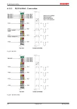
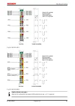
Страница 66: ...Mounting and wiring EL33xx 00x0 66 Version 4 2 4 13 3 EL3314 00x0 Connection Fig 50 EL3314 Fig 51 EL3314 0002...
Страница 103: ...Commissioning EL33xx 00x0 103 Version 4 2 Fig 100 Incorrect driver settings for the Ethernet port...
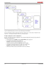
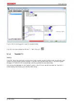
Страница 114: ...Commissioning EL33xx 00x0 114 Version 4 2 Fig 119 EtherCAT terminal in the TwinCAT tree left TwinCAT 2 right TwinCAT 3...

