Mounting and wiring
EL33xx-00x0
52
Version: 4.2
4.8.2
Wiring
WARNING
Risk of electric shock and damage of device!
Bring the bus terminal system into a safe, powered down state before starting installation, disassembly or
wiring of the Bus Terminals!
Terminals for standard wiring ELxxxx/KLxxxx and for pluggable wiring ESxxxx/KSxxxx
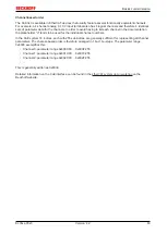
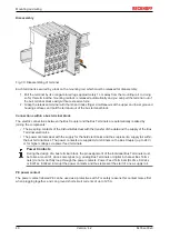
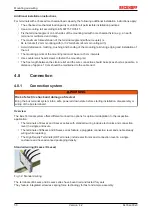
Fig. 35: Connecting a cable on a terminal point
Up to eight terminal points enable the connection of solid or finely stranded cables to the Bus Terminal. The
terminal points are implemented in spring force technology. Connect the cables as follows:
1. Open a terminal point by pushing a screwdriver straight against the stop into the square opening
above the terminal point. Do not turn the screwdriver or move it alternately (don't toggle).
2. The wire can now be inserted into the round terminal opening without any force.
3. The terminal point closes automatically when the pressure is released, holding the wire securely and
permanently.
See the following table for the suitable wire size width.
Terminal housing
ELxxxx, KLxxxx
ESxxxx, KSxxxx
Wire size width (single core wires)
0.08 ... 2.5 mm
2
0.08 ... 2.5 mm
2
Wire size width (fine-wire conductors)
0.08 ... 2.5 mm
2
0,08 ... 2.5 mm
2
Wire size width (conductors with a wire end sleeve)
0.14 ... 1.5 mm
2
0.14 ... 1.5 mm
2
Wire stripping length
8 ... 9 mm
9 ... 10 mm
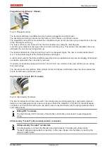
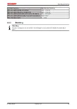
High Density Terminals (
) with 16 terminal points
The conductors of the HD Terminals are connected without tools for single-wire conductors using the direct
plug-in technique, i.e. after stripping the wire is simply plugged into the terminal point. The cables are
released, as usual, using the contact release with the aid of a screwdriver. See the following table for the
suitable wire size width.
Содержание EL33-00 Series
Страница 2: ......
Страница 6: ...Table of contents EL33xx 00x0 6 Version 4 2...
Страница 17: ...Product overview EL33xx 00x0 17 Version 4 2 Fig 10 EL3312 Fig 11 EL3314...
Страница 18: ...Product overview EL33xx 00x0 18 Version 4 2 Fig 12 EL3314 0002 Fig 13 EL3314 0010...
Страница 60: ...Mounting and wiring EL33xx 00x0 60 Version 4 2 4 12 3 EL3314 EL3314 00xx LEDs Fig 43 EL3314 Fig 44 EL3314 0002...
Страница 61: ...Mounting and wiring EL33xx 00x0 61 Version 4 2 Fig 45 EL3314 0010 Fig 46 EL3314 0090...
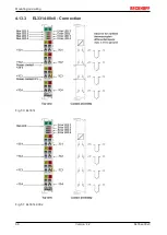
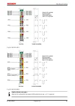
Страница 66: ...Mounting and wiring EL33xx 00x0 66 Version 4 2 4 13 3 EL3314 00x0 Connection Fig 50 EL3314 Fig 51 EL3314 0002...
Страница 103: ...Commissioning EL33xx 00x0 103 Version 4 2 Fig 100 Incorrect driver settings for the Ethernet port...
Страница 114: ...Commissioning EL33xx 00x0 114 Version 4 2 Fig 119 EtherCAT terminal in the TwinCAT tree left TwinCAT 2 right TwinCAT 3...

