background image

Item

Description

Definition

6

CAS latency

P = CAS 15-15-15

T = CAS 17-17-17

U = CAS 20-18-18

V = CAS 19-19-19 (for RDIMM, LRDIMM)

V = CAS 22-19-19 (for 3DS TSVLRDIMM)

7

DIMM type

R = RDIMM (registered)

L = LRDIMM (load reduced)

E = Unbuffered ECC (UDIMM)

For more information about product features, specifications, options, configurations, and compatibility, see the
product QuickSpecs on the Hewlett Packard Enterprise website (

http://www.hpe.com/info/qs

).

Installing a DIMM

The server supports up to 24 DIMMs.

Prerequisites

Before installing this option, be sure you have the following:

The components included with the hardware option kit

For more information on specific options, see the server QuickSpecs on the 

Hewlett Packard Enterprise

website

.

Procedure

1.

Power down the server

.

2.

Remove all power:

a.

Disconnect each power cord from the power source.

b.

Disconnect each power cord from the server.

3.

Do one of the following:

a. Extend the server from the rack

.

b. Remove the server from the rack

.

4.

Remove the access panel

.

5.

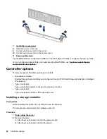
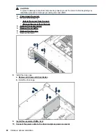
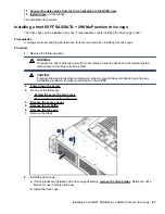
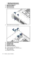
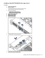
Open the DIMM slot latches.

6.

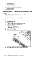
Install the DIMM.

Installing a DIMM

61

Содержание BCD221

Страница 1: ...R OEM USER GUIDE This document is for the person who installs administers and troubleshoots servers and storage systems BCDVIDEO assumes you are qualified in the servicing of computer equipment and trained in recognizing hazards in products with hazardous energy levels ...

Страница 2: ...e for technical or editorial errors or omissions contained herein Confidential computer software Valid license from Hewlett Packard Enterprise required for possession use or copying Consistent with FAR 12 211 and 12 212 Commercial Computer Software Computer Software Documentation and Technical Data for Commercial Items are licensed to the U S Government under vendor s standard commercial license L...

Страница 3: ...ontroller 26 Drive bay numbering SAS expander 28 Drive bay numbering NVMe drives 30 uFF drive bay numbering 31 Operations 32 Powering up the server 32 Power down the server 32 Extend the server from the rack 32 Extending the server from the rack 33 Removing the server from the rack 34 Installing the server into the rack 34 Remove the access panel 36 Installing the access panel 36 Removing the fan ...

Страница 4: ...rt Memory speed information 60 DIMM label identification 60 Installing a DIMM 61 Controller options 62 Installing a storage controller 62 Installing a Universal Media Bay 63 Drive cage options 65 Installing a front 8NVMe SSD Express Bay drive cage 65 Installing a front 6SFF SAS SATA 2NVMe Premium drive cage 67 Installing airflow labels 68 Installing a front 8SFF SAS SATA drive cage in box 1 69 Ins...

Страница 5: ...nt 2SFF drive option for LFF 121 Cable routing Front 2SFF drive options 3 position cable 122 Cable routing Front 8SFF drive options 123 Cable routing Front 8SFF NVMe SAS premium drive option 125 Cable routing Front 8SFF NVMe drive options 125 Cable routing Front 2SFF NVMe drive option for SFF 127 Cable routing Front 2SFF NVMe drive option for LFF 128 Cable routing Midplane 4LFF drive option 128 Ca...

Страница 6: ...ulatory information 145 Safety and regulatory compliance 145 Warranty information 145 Regulatory information 145 Belarus Kazakhstan Russia marking 145 Turkey RoHS material content declaration 146 Ukraine RoHS material content declaration 146 Specifications 147 Environmental specifications 147 Mechanical specifications 147 Power supply specifications 148 HPE 500W Flex Slot Platinum Hot plug Power S...

Страница 7: ...Documentation feedback 157 Contents 7 ...

Страница 8: ...or universal media bay 2 Box 2 optional drives 3 Box 3 Drives 1 8 4 Serial label pull tab or optional Systems Insight Display 5 iLO service port 6 USB 3 0 port Universal media bay components Item Description 1 USB 2 0 port 2 Video display port 3 Optical disk drive optional 4 Drives optional 8 Component identification ...

Страница 9: ...anel components Item Description 1 Drive bays 8 drive LFF model front panel components Item Description 1 Drives optional 2 LFF power switch module 3 Drive bays LFF power switch module components Component identification 9 ...

Страница 10: ...tatus 1 Power On Standby button and system power LED Solid green System on Flashing green 1 Hz cycle per sec Performing power on sequence Solid amber System in standby Off No power present 2 Health LED Solid green Normal Flashing green 1 Hz cycle per sec iLO is rebooting Flashing amber System degraded Flashing red 1 Hz cycle per sec System critical Table Continued 10 Front panel LEDs and buttons ...

Страница 11: ...nual reboot sequence in progress Off Deactivated When all four LEDs described in this table flash simultaneously a power fault has occurred For more information see Power fault LEDs If the health LED indicates a degraded or critical state review the system IML or use iLO to review the system health status Facility power is not present power cord is not attached no power supplies are installed powe...

Страница 12: ...button LED Solid blue Activated Flashing blue 1 Hz cycle per sec Remote management or firmware upgrade in progress 4 Hz cycle per sec iLO manual reboot sequence initiated 8 Hz cycle per sec iLO manual reboot sequence in progress Off Deactivated When all four LEDs described in this table flash simultaneously a power fault has occurred For more information see Power fault LEDs If the health LED indi...

Страница 13: ...ycle per sec iLO is rebooting Flashing amber System degraded Flashing red 1 Hz cycle per sec System critical 3 NIC status LED Solid green Link to network Flashing green 1 Hz cycle per sec Network active Off No network activity 4 Power On Standby button and system power LED Solid green System on Flashing green 1 Hz cycle per sec Performing power on sequence Solid amber System in standby Off No powe...

Страница 14: ...Packard Enterprise website Power fault LEDs The following table provides a list of power fault LEDs and the subsystems that are affected Not all power faults are used by all servers Subsystem LED behavior System board 1 flash Processor 2 flashes Memory 3 flashes Riser board PCIe slots 4 flashes FlexibleLOM 5 flashes Removable HPE Flexible Smart Array controller Smart SAS HBA controller 6 flashes S...

Страница 15: ...ge Over temp LED Off Normal Amber High system temperature detected Amp Status LED Off AMP modes disabled Solid green AMP mode enabled Solid amber Failover Flashing amber Invalid configuration Power cap LED Off System is in standby or no cap is set Solid green Power cap applied When the health LED on the front panel illuminates either amber or red the server is experiencing a health event For more ...

Страница 16: ...The server has detected a hardware critical temperature level PCI riser amber Red Green The PCI riser cage is not seated properly Fan amber Amber Green One fan has failed or has been removed Fan amber Red Green Two or more fans have failed or been removed Power supply amber Red Amber One or more of the following conditions may exist Only one power supply is installed and that power supply is in st...

Страница 17: ... by removing all other DIMMs Isolate the failed DIMM by replacing each DIMM in a bank with a known working DIMM Rear panel components Item Description 1 Primary riser slots 1 3 Optional drive cage 2 Optional riser slots 4 6 Optional drive cage 3 Optional riser slots 7 8 Optional drive cage 4 Power supply 1 5 Power supply 2 6 Video port 7 Serial port optional 8 1Gb RJ 45 ports 1 4 9 iLO management ...

Страница 18: ...shing blue System being managed remotely 2 Link LED Off No network link Green Network link 3 Activity LED Off No network activity Solid green Link to network Flashing green Network activity 4 Power supply LEDs Off System is off or power supply has failed Solid green Normal 18 Rear panel LEDs ...

Страница 19: ...stem board components Item Description 1 FlexibleLOM connector 2 System maintenance switch 3 Primary PCIe riser connector 4 Front display port USB 2 0 connector Table Continued System board components 19 ...

Страница 20: ...a Smart Array connector 18 Secondary PCIe riser connector 19 System battery 20 Tertiary PCIe riser connector 21 TPM connector 22 Serial port connector optional Requires a second processor System maintenance switch descriptions Position Default Function S1 1 Off Off iLO security is enabled On iLO security is disabled S2 Reserved S3 Off Reserved S4 Off Reserved S51 Off Off Power on password is enabl...

Страница 21: ...onfiguration settings to their manufacturing defaults When the system maintenance switch position 6 is set to the On position and Secure Boot is enabled some configurations cannot be restored For more information see Secure Boot configuration Processor heatsink and socket components Item Description 1 Heatsink nuts 2 Processor frame 3 Pin 1 indicator1 4 Heatsink latch 5 Alignment post 1 Symbol als...

Страница 22: ...ail Off Removing the drive does not cause a logical drive to fail 4 Drive status LED Solid green The drive is a member of one or more logical drives Flashing green The drive is rebuilding or performing a RAID migration strip size migration capacity expansion or logical drive extension or is erasing Flashing amber green The drive is a member of one or more logical drives and predicts the drive will...

Страница 23: ...to indicate the device is still in use Removal of the NVMe SSD before the device has completed and ceased signal traffic flow can cause loss of data uFF drive components and LEDs Item Description Status 1 Locate Off Normal Solid blue The drive is being identified by a host application Flashing blue The drive firmware is being updated or requires an update 2 uFF drive ejection latch Removes the uFF...

Страница 24: ...ashing green 4 Hz The drive is operating normally and has activity Flashing green 1 Hz The drive is rebuilding or performing a RAID migration stripe size migration capacity expansion logical drive extension or is erasing Flashing amber green 1 Hz The drive is a member of one or more logical drives that predicts the drive will fail Solid amber The drive has failed Flashing amber 1 Hz The drive is n...

Страница 25: ...Drive box identification Front boxes Item Description 1 Box 1 2 Box 2 3 Box 3 Item Description 1 Box 1 2 Box 2 3 Box 3 Rear boxes Item Description 1 Box 4 2 Box 5 3 Box 6 Drive box identification 25 ...

Страница 26: ...nboard SATA ports Type a controllers install to the type a smart array connector Type p controllers install to a PCIe riser To a SAS expander Installs in the primary or secondary PCIe riser Drive bay numbering Smart Array controller When the drive backplane is connected directly to a storage controller then each drive box starts at 1 The following images are examples of common configurations 26 Dr...

Страница 27: ...Component identification 27 ...

Страница 28: ... connects to port 2 of the controller SAS expander port 3 drive numbers 1 4 SAS expander port 4 drive numbers 5 8 SAS expander port 5 drive numbers 9 12 SAS expander port 6 drive numbers 13 16 SAS expander port 7 drive numbers 17 20 SAS expander port 8 drive numbers 21 24 SAS expander port 9 drive numbers 25 28 Common configuration examples 28 Drive bay numbering SAS expander ...

Страница 29: ...ring on page 31 For example when a rear 2SFF drive cage is connected to SAS expander port 9 then the drive numbers are 25 and 27 When the front 24SFF bays are populated any installed rear 2SFF drives are always 25 and 27 If a 2SFF drive cage is connected to SAS expander port 3 then the drive numbers are 1 and 3 Component identification 29 ...

Страница 30: ...Front 12LFF Midplane 4LFF All rear 2SFF Drive bay numbering NVMe drives If the server is populated with NVMe drives and NVMe risers 30 Drive bay numbering NVMe drives ...

Страница 31: ...t bay number of the server The right bay The default bay number of the server 100 If the drives are connected to a SAS expander For example If the drives are connected to port 3 of the SAS expander then the uFF drives are 1 4 If the drives are connected to port 9 of the SAS expander then the uFF drives are 25 28 uFF drive bay numbering 31 ...

Страница 32: ...han 4 seconds to force the server to enter standby mode This method forces the server to enter standby mode without properly exiting applications and the OS If an application stops responding you can use this method to force a shutdown Use a virtual power button selection through iLO This method initiates a controlled remote shutdown of applications and the OS before the server enters standby mode...

Страница 33: ...ver rail release latches and sliding the server into the rack The sliding rails could pinch your fingers Extending the server from the rack WARNING To reduce the risk of personal injury or equipment damage be sure that the rack is adequately stabilized before extending anything from the rack Procedure 1 Pull down the quick release levers on each side of the server and then extend the server from t...

Страница 34: ...ation so that the heaviest item is on the bottom of the rack Install the heaviest item first and continue to populate the rack from the bottom to the top 2 Install the server and cable management arm into the rack For more information see the installation instructions that ship with the 2U Quick Deploy Rail System 3 Connect peripheral devices to the server For information on identifying connectors...

Страница 35: ...k or damage to the equipment Do not disable the power cord grounding plug The grounding plug is an important safety feature Plug the power cord into a grounded earthed electrical outlet that is easily accessible at all times Unplug the power cord from the power supply to disconnect power to the equipment Do not route the power cord where it can be walked on or pinched by items placed against it Pa...

Страница 36: ...rver with the latch open Allow the panel to extend past the rear of the server approximately 1 25 cm 0 5 in 2 Push down on the latch The access panel slides to a closed position 3 Tighten the security screw on the latch Removing the fan cage CAUTION Do not operate the server for long periods with the access panel open or removed Operating the server in this manner results in improper airflow and i...

Страница 37: ...er airflow and improper cooling that can lead to thermal damage IMPORTANT For optimum cooling install fans in all primary fan locations Removing the air baffle or midplane drive cage CAUTION Do not detach the cable that connects the battery pack to the cache module Detaching the cable causes any unsaved data in the cache module to be lost Installing the fan cage 37 ...

Страница 38: ... from the server 3 Do one of the following Extend the server from the rack Remove the server from the rack 4 Remove the access panel 5 Do one of the following Remove the air baffle Remove the 4LFF midplane drive cage a Disconnect all cables b Remove all drives Be sure to note the location of each drive c Remove the drive cage CAUTION Do not drop the drive cage on the system board Dropping the driv...

Страница 39: ...es expansion slot covers or blanks installed If the server supports hot plug components minimize the amount of time the access panel is open CAUTION Do not detach the cable that connects the battery pack to the cache module Detaching the cable causes any unsaved data in the cache module to be lost 2 Install the air baffle Installing the air baffle 39 ...

Страница 40: ...ser cage Procedure 1 Power down the server 2 Remove all power a Disconnect each power cord from the power source b Disconnect each power cord from the server 3 Do one of the following Extend the server from the rack Remove the server from the rack 4 Remove the access panel 5 Remove the riser cage Primary and secondary riser cages Tertiary riser cage 40 Removing a riser cage ...

Страница 41: ...rocedure 1 Power down the server 2 Remove all power a Disconnect each power cord from the power source b Disconnect each power cord from the server 3 Do one of the following Extend the server from the rack Remove the server from the rack 4 Remove the access panel 5 Remove the riser cage 6 Remove the blank Removing the hard drive blank Remove the component as indicated Removing a riser slot blank 4...

Страница 42: ...k Accessing the Systems Insight Display The Systems Insight Display is only supported on SFF models To access a Systems Insight Display use the following procedure Procedure 1 Press and release the panel 2 After the display fully ejects rotate the display to view the LEDs 42 Releasing the cable management arm ...

Страница 43: ...Operations 43 ...

Страница 44: ...dware and software HPE Education Services Help train your IT staff For more information on HPE support services see the Hewlett Packard Enterprise website Setup overview Procedure 1 Review the operational requirements for the server Operational requirements on page 44 2 Read the following safety notices warnings and cautions Server warnings and cautions Server warnings and cautions on page 46 Rack...

Страница 45: ...Series Racks provide proper server cooling from flow through perforations in the front and rear doors that provide 64 percent open area for ventilation CAUTION When using a Compaq branded 7000 series rack install the high airflow rack door insert PN 327281 B21 for 42U rack PN 157847 B21 for 22U rack to provide proper front to back airflow and cooling CAUTION If a third party rack is used observe t...

Страница 46: ...e 250 as well as any local and regional building codes In Canada you must install the equipment in accordance with Canadian Standards Association CSA C22 1 Canadian Electrical Code In all other countries you must install the equipment in accordance with any regional or national electrical wiring codes such as the International Electrotechnical Commission IEC Code 364 parts 1 through 7 Furthermore ...

Страница 47: ...eling jacks The stabilizing feet are attached to the rack if it is a single rack installation The racks are coupled together in multiple rack installations Only one component is extended at a time A rack may become unstable if more than one component is extended for any reason WARNING To reduce the risk of personal injury or equipment damage when unloading a rack At least two people are needed to ...

Страница 48: ... mounting hardware Documentation Installing hardware options Install any hardware options before initializing the server For options installation information refer to the option documentation For server specific information refer to Hardware options installation Configuring the server When the server is powered on the POST screen is displayed Use the following options to configure the server Syste...

Страница 49: ...website The server does not ship with OS media All system software and firmware is preloaded on the server Registering the server To experience quicker service and more efficient support register the product at the Hewlett Packard Enterprise Product Registration website Registering the server 49 ...

Страница 50: ...installation instructions for all the hardware options and identify similar steps to streamline the installation process WARNING To reduce the risk of personal injury from hot surfaces allow the drives and the internal system components to cool before touching them CAUTION To prevent damage to electrical components properly ground the server before beginning any installation procedure Improper gro...

Страница 51: ...city Verify that all power supplies have the same part number and label color The system becomes unstable and might shut down if it detects different power supplies CAUTION To prevent improper cooling and thermal damage do not operate the server unless all bays are populated with either a component or a blank Procedure 1 Release the cable management arm to access the rear panel 2 Remove the blank ...

Страница 52: ...Drive options Drive guidelines Depending on the configuration the server supports SAS SATA and NVMe drives Observe the following general guidelines The system automatically sets all drive numbers If only one hard drive is used install it in the bay with the lowest drive number For drive numbering see Drive bay numbering The NVMe SSD is a PCIe bus device Devices attached to a PCIe bus cannot be rem...

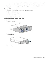
Страница 53: ...ives with the same capacity provide the greatest storage space efficiency when grouped into the same drive array Supported drive carriers Depending on the drive cage the server supports the following drive carriers SFF Smart Carrier SC SFF Smart Carrier NVMe SCN SFF Smart Carrier M 2 SCM LFF Smart Carrier SC LFF to SFF Smart Carrier Converter Installing a hot plug SAS or SATA drive Procedure 1 Rem...

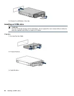
Страница 54: ...CAUTION To prevent improper cooling and thermal damage do not operate the server unless all drive and device bays are populated with either a component or a blank Procedure 1 Remove the drive blank 2 Prepare the drive 3 Install the drive 54 Installing an NVMe drive ...

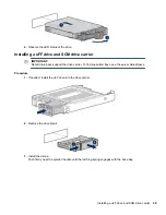
Страница 55: ...t the drive carrier To find supported bays see the server QuickSpecs Procedure 1 If needed install the uFF drive into the drive carrier 2 Remove the drive blank 3 Install the drives Push firmly near the ejection handle until the latching spring engages with the drive bay Installing a uFF drive and SCM drive carrier 55 ...

Страница 56: ...fore installing this option be sure that you have the following The components included with the hardware option kit T 10 Torx screwdriver Procedure 1 Power down the server 2 Remove all power a Disconnect each power cord from the power source b Disconnect each power cord from the server 3 Do one of the following Extend the server from the rack Remove the server from the rack 4 Remove the access pa...

Страница 57: ...onfigurations six fans are required for redundancy A fan failure or missing fan causes a loss of redundancy A second fan failure or missing fan causes an orderly shutdown of the server High performance fans might be necessary in 24 SFF and 12 LFF configurations for the following installations Optional GPU riser installations ASHRAE compliant configurations For more information see the Hewlett Pack...

Страница 58: ...ess panel open or removed Operating the server in this manner results in improper airflow and improper cooling that can lead to thermal damage Procedure 1 Extend the server from the rack 2 Remove the access panel 3 If installed remove all fan blanks 4 Remove the air baffle 5 Remove all standard fans IMPORTANT Do not mix standard fans and high performance fans in the same server 58 Installing high ...

Страница 59: ...g LRDIMMs and RDIMMs Attempting to mix any combination of these DIMMs can cause the server to halt during BIOS initialization All memory installed in the server must be of the same type DIMM population information For specific DIMM population information see the DIMM population guidelines on the Hewlett Packard Enterprise website http www hpe com docs memory population rules Memory options 59 ...

Страница 60: ...el attached to the DIMM The information in this section helps you to use the label to locate specific information about the DIMM Item Description Definition 1 Capacity 8 GB 16 GB 32 GB 64 GB 128 GB 2 Rank 1R Single rank 2R Dual rank 4R Quad rank 8R Octal rank 3 Data width on DRAM x4 4 bit x8 8 bit x16 16 bit 4 Memory generation PC4 DDR4 5 Maximum memory speed 2133 MT s 2400 MT s 2666 MT s Table Co...

Страница 61: ...stalling a DIMM The server supports up to 24 DIMMs Prerequisites Before installing this option be sure you have the following The components included with the hardware option kit For more information on specific options see the server QuickSpecs on the Hewlett Packard Enterprise website Procedure 1 Power down the server 2 Remove all power a Disconnect each power cord from the power source b Discon...

Страница 62: ...storage controllers Embedded controllers Enabled through System Utilities and configured through HPE Smart Storage Administrator Intelligent Provisioning Type a controllers Type a controllers install in the type a smart array connector Type p controllers Type p controllers install in a PCIe expansion slot Installing a storage controller Prerequisites Before installing this option be sure that you ...

Страница 63: ...ansion slot 7 Cable the controller The installation is complete Installing a Universal Media Bay Prerequisites Before installing this option be sure that you have the following The components included with the hardware option kit T 10 Torx screwdriver Procedure 1 Power down the server 2 Remove all power a Disconnect each power cord from the power source b Disconnect each power cord from the server...

Страница 64: ...ute the USB and video cables through the opening 9 If installing a two bay SFF front drive cage install the drive cage 10 Install the universal media bay 11 Optional Install the optical disk drive 64 Hardware options installation ...

Страница 65: ...procedure covers installing the drive cage in box 1 When installing in box 1 the NVMe riser must be installed in the tertiary PCIe slot When installing in box 2 the NVMe riser must be installed in the secondary PCIe slot When installing in box 3 the NVMe riser must be installed in the primary PCIe slot Prerequisites An associated NVMe riser and high performance fans are required when installing th...

Страница 66: ... the following Extend the server from the rack Remove the server from the rack 4 Remove the access panel 5 Remove the air baffle 6 Remove the fan cage 7 Remove the blank 8 Install the drive cage a Remove all drives and drive blanks b Install the drive cage 9 Install the associated NVMe riser 10 Connect the power cable to the drive backplane power connector 66 Hardware options installation ...

Страница 67: ...surfaces allow the drives and the internal system components to cool before touching them CAUTION To prevent damage to electrical components properly ground the server before beginning any installation procedure Improper grounding can cause ESD 2 Power down the server 3 Do one of the following Extend the server from the rack Remove the server from the rack 4 Remove the access panel 5 Remove the ai...

Страница 68: ...talled airflow labels might be required Prerequisites Before installing this option be sure that you have the following The components included with the hardware option kit Procedure If an eight bay SFF drive cage is installed in box 1 then airflow labels are not required If a blank is installed in box 1 replace it with the blank that comes with the kit If a Universal Media Bay is installed in box...

Страница 69: ...e in box 1 Prerequisites Before installing this option be sure that you have the following T 10 Torx screwdriver The components included with the hardware option kit Procedure 1 Power down the server 2 Remove all power a Disconnect each power cord from the power source b Disconnect each power cord from the server 3 Do one of the following Installing a front 8SFF SAS SATA drive cage in box 1 69 ...

Страница 70: ... Install the 8SFF front drive cage option 9 Connect the power and data cables 10 Install the fan cage 11 Install the air baffle 12 Install the access panel 13 Slide the server into the rack 14 Connect each power cord to the server 15 Connect each power cord to the power source 16 Power up the server The installation ins complete 70 Hardware options installation ...

Страница 71: ...isconnect each power cord from the server 3 Do one of the following Extend the server from the rack Remove the server from the rack 4 Remove the access panel 5 Remove the air baffle 6 Remove the fan cage 7 Remove the bay blank 8 Install the 8SFF front drive cage option 9 Connect the power and data cables Installing a front 8SFF SAS SATA drive cage in box 2 71 ...

Страница 72: ... following T 10 Torx screwdriver The components included with the hardware option kit This installation requires a universal media bay Procedure 1 Power down the server 2 Remove all power a Disconnect each power cord from the power source b Disconnect each power cord from the server 3 Do one of the following Extend the server from the rack Remove the server from the rack 4 Remove the access panel ...

Страница 73: ...7 Remove the SFF drive blank from the universal media bay 8 Install the drive cage into the universal media bay Hardware options installation 73 ...

Страница 74: ...9 Install the optical disk drive tray 10 Install the universal media bay 74 Hardware options installation ...

Страница 75: ...tion If you have a type a controller install it prior to this option Prerequisites Before installing this option be sure that you have the following The components included with the hardware option kit Procedure 1 Power down the server 2 Remove all power a Disconnect each power cord from the power source b Disconnect each power cord from the server 3 Do one of the following Extend the server from ...

Страница 76: ...ve cage on the system board Dropping the drive cage on the system board might damage the system or components Remove all drives and use two hands when installing or removing the drive cage a Locate the alignment pins on the rear of the drive cage b Align the pin on the rear left of the drive cage to the server and then insert the pin c Gently lower the opposite side of the drive cage d Pull the pl...

Страница 77: ...SAS SATA drive cage in the primary or secondary riser Prerequisites Before installing this option be sure that you have the following T 10 Torx screwdriver The components included with the hardware option kit The front drive bays are fully populated with 12 LFF or 24 SFF drives High performance fans are installed in all fan bays Installing a rear 2SFF SAS SATA drive cage in the primary or secondar...

Страница 78: ...ver 3 Do one of the following Extend the server from the rack Remove the server from the rack 4 Remove the access panel 5 Do one of the following For primary bays remove the riser cage For secondary bays remove the rear wall blank 6 Install a SAS expander or other expansion card if needed 7 Install the drive cage 78 Hardware options installation ...

Страница 79: ...llowing T 10 Torx screwdriver The components included with the hardware option kit The front bays are fully populated with 12 LFF or 24 SFF drives High performance fans are installed in all fan bays Procedure 1 Power down the server 2 Remove all power a Disconnect each power cord from the power source b Disconnect each power cord from the server 3 Do one of the following Extend the server from the...

Страница 80: ...Remove the secondary wall blank 6 Remove the tertiary wall blank 80 Hardware options installation ...

Страница 81: ...7 Install the drive cage compatible rear wall 8 Install the drive cage Hardware options installation 81 ...

Страница 82: ...igh performance fans must be installed in all fan bays Prerequisites Before installing this option be sure that you have the following T 10 Torx screwdriver The components included with the hardware option kit Procedure 1 Power down the server 2 Remove all power a Disconnect each power cord from the power source b Disconnect each power cord from the server 3 Do one of the following Extend the serv...

Страница 83: ...6 Remove the rear wall blank 7 Install the three bay LFF rear drive cage option Hardware options installation 83 ...

Страница 84: ...d secondary risers Prerequisites Before installing this option be sure that you have the following The components included with the hardware option kit T 10 Torx screwdriver Procedure 1 Power down the server 2 Do one of the following Disconnect each power cord from the power source Disconnect each power cord from the server 3 Do one of the following Extend the server from the rack Remove the serve...

Страница 85: ...bles to drive backlanes The installation is complete Installing tertiary risers Prerequisites Before installing this option be sure that you have the following The components included with the hardware option kit T 10 Torx screwdriver A tertiary riser cage is required to install this option Procedure 1 Power down the server 2 Do one of the following Installing tertiary risers 85 ...

Страница 86: ...eeded The installation is complete Installing a secondary riser cage Prerequisites Before installing this option be sure that you have the following The components included with the hardware option kit T 10 Torx screwdriver Procedure 1 Observe the following alert CAUTION To prevent damage to the server or expansion boards power down the server and remove all AC power cords before removing or insta...

Страница 87: ...k 7 Install any expansion boards if needed 8 Install the riser cage The installation is complete Installing a tertiary riser cage Prerequisites Before installing this option be sure that you have the following The components included with the hardware option kit T 10 Torx screwdriver Installing a tertiary riser cage 87 ...

Страница 88: ... the PCI riser cage 2 Power down the server 3 Remove all power a Disconnect each power cord from the power source b Disconnect each power cord from the server 4 Do one of the following Extend the server from the rack Remove the server from the rack 5 Remove the access panel 6 Remove the rear wall blanks 7 Install the rear blank from the option kit 88 Hardware options installation ...

Страница 89: ...e Installing the 2NVMe slimSAS riser option Prerequisites Before installing this option be sure that you have the following The components included with the hardware option kit T 10 Torx screwdriver Procedure 1 Power down the server 2 Do one of the following Installing the 2NVMe slimSAS riser option 89 ...

Страница 90: ...e installed in the primary or secondary position Prerequisites Before installing this option be sure that you have the following The components included with the hardware option kit T 10 Torx screwdriver Procedure 1 Power down the server 2 Do one of the following Disconnect each power cord from the power source Disconnect each power cord from the server 3 Do one of the following Extend the server ...

Страница 91: ...ndary riser cage 7 Connect data cables to the drive backplane Expansion slots Supported PCIe form factors All slots support full height expansion cards Use the following information to find supported lengths for each slot Slot description example Expansion slots 91 ...

Страница 92: ...PCIe3 x8 8 4 2 1 PCIe3 x16 16 8 4 2 1 Tertiary riser connector PCIe slot and card length 2 slot riser Optional 1 slot riser Optional Slot 7 Full length Full height FL FH PCIe3 x8 8 4 2 1 PCIe3 x16 16 8 4 2 1 Slot 8 Half length Full height HL FH PCIe3 x8 8 4 2 1 Installing expansion boards WARNING To reduce the risk of personal injury electric shock or damage to the equipment remove the power cord ...

Страница 93: ...Disconnect each power cord from the server 3 Do one of the following Extend the server from the rack Remove the server from the rack 4 Remove the access panel 5 Remove the riser cage 6 Identify and then remove the PCIe blank from the riser cage 7 Install the expansion board Hardware options installation 93 ...

Страница 94: ...e cages in boxes 1 and 2 For configurations including a 2SFF rear drive cage install the drive cage over the power supplies HPE recommends installing the SAS expander card into slot 3 of the primary PCIe riser expansion card To ensure that cables are connected correctly observe the labels on the cable and port Be sure that you have the latest firmware for the controllers and the expander card To d...

Страница 95: ...move the fan cage 7 Remove the riser cage 8 Locate slot 3 and then remove the expansion slot blank 9 Install the 12G SAS expander card IMPORTANT The 12G SAS expander card requires a controller The server supports embedded type a and type p Smart Array controllers If using a type p Smart Array controller then install the controller in slot 1 10 Using the labels on each cable connect the cables to t...

Страница 96: ...all the air baffle 16 Install the access panel 17 Install the server into the rack 18 Connect each power cord to the server 19 Connect each power cord to the power source 20 Power up the server The installation is complete Installing a GPU card A GPU can be installed into the primary secondary or tertiary position This procedure shows installation in the secondary position 96 Installing a GPU card...

Страница 97: ...ve either an expansion slot cover or an expansion board installed 2 Power down the server 3 Remove all power a Disconnect each power cord from the power source b Disconnect each power cord from the server 4 Do one of the following Extend the server from the rack Remove the server from the rack 5 Remove the access panel 6 Remove the air baffle 7 Remove the air diverters from the air baffle 8 Instal...

Страница 98: ...high performance heatsinks 10 Install the air baffle 11 Remove the rear wall blank To install a tertiary GPU remove the 12 Remove the PCIe blank 13 Install the GPU into the riser 98 Hardware options installation ...

Страница 99: ...14 Connect the power cable from the GPU to the riser 15 Slide the retention clips to the unlocked position 16 Install the riser cage Hardware options installation 99 ...

Страница 100: ...Before installing this option be sure that you have the following The components included with the hardware option kit Procedure 1 Power down the server 2 Remove all power a Disconnect each power cord from the power source b Disconnect each power cord from the server 3 Do one of the following 100 Installing an intrusion detection switch ...

Страница 101: ... included with the hardware option kit Procedure 1 Power down the server 2 Do one of the following Disconnect each power cord from the power source Disconnect each power cord from the server 3 Do one of the following Extend the server from the rack Remove the server from the rack 4 Remove the access panel 5 Do one of the following Remove the air baffle If installed on LFF models remove the midplan...

Страница 102: ...h power cord to the power source 14 Power up the server The installation is complete Installing a rear serial port interface If a tertiary riser cage is installed you can install the serial port into the slot 6 Prerequisites Before installing this option be sure that you have the following The components included with the hardware option kit 102 Installing a rear serial port interface ...

Страница 103: ...e of the following Extend the server from the rack Remove the server from the rack 4 Remove the access panel 5 Do one of the following If a tertiary riser cage is not installed install the serial port Be sure to remove the backing from the double sided tape If a tertiary riser cage is installed remove the riser and the blank Hardware options installation 103 ...

Страница 104: ...Connect each power cord to the power source 10 Power up the server The installation is complete Installing a Systems Insight Display Prerequisites Before installing this option be sure that you have the following The components included with the hardware option kit T 10 Torx screwdriver 104 Installing a Systems Insight Display ...

Страница 105: ...If installed on LFF models remove the midplane drive cage 6 Remove the fan cage 7 Disconnect the cable from the front power USB 3 0 connector 8 Remove the power switch module Retain the T 10 screw for later use 9 Route the cable through the opening in the front of the server and then install the SID power switch module Secure the module using the existing screw CAUTION When routing cables always b...

Страница 106: ...ling a FlexibleLOM adapter Prerequisites The components included with the hardware option kit A T 10 Torx screwdriver might be needed to unlock the access panel Procedure 1 Power down the server 2 Do one of the following Disconnect each power cord from the power source Disconnect each power cord from the server 3 Do one of the following Extend the server from the rack Remove the server from the ra...

Страница 107: ...stall the access panel 10 Slide the server into the rack 11 Connect the LAN segment cables 12 Connect each power cord to the server 13 Connect each power cord to the power source 14 Power up the server The installation is complete Hardware options installation 107 ...

Страница 108: ...aster speed update the system ROM before installing the processor To download firmware and view installation instructions see the Hewlett Packard Enterprise Support Center website CAUTION THE CONTACTS ARE VERY FRAGILE AND EASILY DAMAGED To avoid damage to the socket or processor do not touch the contacts 2 Power down the server 3 Remove all power a Disconnect each power cord from the power source ...

Страница 109: ... 4 flathead screwdriver into the release slot Be sure that the screwdriver is between the plastic frame and the heatsink c To lift the processor frame away from the heatsink slowly rotate the screwdriver d Unlatch the remaining corners of the frame e Separate the frame from the heatsink 9 Using an alcohol wipe remove the existing thermal grease Allow solvent to dry before making contact with therm...

Страница 110: ... it along the top and bottom of the fins Holding it from the sides can damage the fins CAUTION To avoid damage to the processor or system board only authorized personnel should attempt to replace or install the processor in this server CAUTION To prevent possible server malfunction and damage to the equipment multiprocessor configurations must contain processors with the same part number CAUTION I...

Страница 111: ...ne of the following Remove the air baffle If installed remove the 4LFF midplane drive cage 7 Install the processor heatsink assembly a Remove the dust cover b Locate the Pin 1 indicator on the processor frame and the socket c Align the processor heatsink assembly with the alignment pins and gently lower it down until it sits evenly on the socket The heatsink alignment pins are keyed The processor ...

Страница 112: ... about Microsoft Windows BitLocker Drive Encryption feature see the Microsoft website http www microsoft com CAUTION Chipset TPM is not available after power is removed from the system and the HPE TPM 2 0 Kit is installed Do not install the HPE TPM 2 0 Kit if Chipset TPM is enabled and the operating system is using Chipset TPM features Otherwise the OS may go into recovery mode data loss can occur...

Страница 113: ...and powered up on a different server data stored in the TPM including keys will be erased When using BitLocker always retain the recovery key password The recovery key password is required to complete Recovery Mode after BitLocker detects a possible compromise of system integrity or system configuration Hewlett Packard Enterprise is not liable for blocked data access caused by improper TPM use For...

Страница 114: ...ack 6 Place the server on a flat level work surface 7 Remove the access panel 8 Do one of the following Remove the air baffle If installed remove the 4LFF midplane drive cage 9 Remove any components or cables that may prevent access to the TPM connector 10 Proceed to Installing the TPM board and cover on page 114 Installing the TPM board and cover Procedure 1 Observe the following alerts CAUTION A...

Страница 115: ...ing the server for operation on page 115 Preparing the server for operation Procedure 1 Install any options or cables previously removed to access the TPM connector 2 Do one of the following Install the air baffle Install the 4LFF midplane drive cage 3 Install the access panel 4 Install the server in the rack 5 Connect power cords to the server 6 Press the Power On Standby button Hardware options ...

Страница 116: ...n graphical mode click Yes If in text mode press the Y key 6 Press the ESC key to exit System Utilities 7 If changes were made and saved the server prompts for reboot request Press the Enter key to confirm reboot If the following actions were performed the server reboots a second time without user input During this reboot the TPM setting becomes effective Changing from TPM 1 2 and TPM 2 0 Changing...

Страница 117: ...rinted after BitLocker is enabled When using BitLocker always retain the recovery key password The recovery key password is required to enter Recovery Mode after BitLocker detects a possible compromise of system integrity To help ensure maximum security observe the following guidelines when retaining the recovery key password Always store the recovery key password in multiple locations Always stor...

Страница 118: ...diagrams For additional cabling configurations see the HPE Information Library http www hpe com info CablingMatrixGen10 Table 1 SAS SATA kits Option kit Cable part number From To Power cable part number Front 2SFF SAS SATA drive cage SFF 869826 001 1 Drive backplane System board SAS Expander Controller 869810 001 6 869825 001 6 Front 2SFF SAS SATA 1U drive cage LFF 869826 001 1 Drive backplane Sys...

Страница 119: ...xpander Kit 875094 001 3 Mini SAS SFF Kit 875089 001 4 SAS 8SFF Kit 784629 001 5 12G SAS Expander to controller kit 875093 001 6 Power cables kit 875096 001 Table 2 NVMe bay riser kits Option kit Cable part number From To Power cable part number Front 2SFF NVMe drive cage NVMe cable included with NVMe riser Drive backplane Tertiary riser 869810 001 3 Front 8SFF SAS SATA NVMe Premium for SFF 776402...

Страница 120: ...Riser HPE GPU 8p Keyed GPU Cable Kit 869820 001 1 GPU Riser HPE GPU 8p Cable Kit 869821 001 1 GPU Riser HPE GPU power adapter 869828 001 1 GPU System board 1 GPU cables kit 875097 001 Table 4 Data kits Option kit Cable part number From To Front USB display port SFF UMB 869804 001 1 Component System board Front USB port SFF UMB 869829 001 1 Component System board Front display port LFF 869808 001 1...

Страница 121: ...Option 2 SAS Expander Option 3 not shown A controller Cable routing Front 2SFF drive option for LFF Option 1 System board Cable routing Front 2SFF drive option for LFF 121 ...

Страница 122: ...Option 2 Controller Option 3 not shown SAS Expander Cable routing Front 2SFF drive options 3 position cable SFF models 122 Cable routing Front 2SFF drive options 3 position cable ...

Страница 123: ...LFF models Cable routing Front 8SFF drive options Box 1 to SAS Expander Cable routing Front 8SFF drive options 123 ...

Страница 124: ...Box 2 to SAS Expander All boxes 124 Cabling ...

Страница 125: ...Cable routing Front 8SFF NVMe SAS premium drive option The backplane shown is in box 3 Cable routing Front 8SFF NVMe drive options Box 1 Cable routing Front 8SFF NVMe SAS premium drive option 125 ...

Страница 126: ...Box 2 Box 3 126 Cabling ...

Страница 127: ...Cable routing Front 2SFF NVMe drive option for SFF Cable routing Front 2SFF NVMe drive option for SFF 127 ...

Страница 128: ...Cable routing Front 2SFF NVMe drive option for LFF Cable routing Midplane 4LFF drive option 128 Cable routing Front 2SFF NVMe drive option for LFF ...

Страница 129: ...drive options Rear 2SFF drive option to a SAS expander both in the primary slot Rear 2SFF drive option in the secondary slot to a SAS Expander in primary slot Rear 2SFF drive option above the power supplies to a controller Cable routing Rear 3LFF drive option 129 ...

Страница 130: ... Observe the following Port 1 always connects to port 1 of the controller Port 2 always connects to port 2 of the controller SAS expander to an a type controller SAS expander to a p type controller 130 Cable routing HPE 12G SAS Expander to a controller ...

Страница 131: ...Cable routing Systems Insight Display An SFF model is shown The routing is the same for LFF Cable routing Systems Insight Display 131 ...

Страница 132: ...s specifications options configurations and compatibility see the product QuickSpecs on the Hewlett Packard Enterprise website http www hpe com info qs Active Health System Viewer Active Health System Viewer AHSV is an online tool used to read diagnose and resolve server issues quickly using AHS uploaded data AHSV provides Hewlett Packard Enterprise recommended repair actions based on experience a...

Страница 133: ...that is collected is managed according to the privacy statement available at http www hpe com info privacy You can also upload the log to the Active Health System Viewer For more information see the Active Health System Viewer documentation at the following website http www hpe com support ahsv docs HPE iLO 5 iLO 5 is a remote server management processor embedded on the system boards of servers an...

Страница 134: ...ccessible by the host operating system Connect a client such as a laptop with a supported USB to Ethernet adapter to access the iLO web interface remote console CLI iLO RESTful API or scripts When you use the iLO Service Port Actions are logged in the iLO Event Log The server UID blinks to indicate the Service Port status You can also retrieve the status by using a REST client and the iLO RESTful ...

Страница 135: ...ith a basic set of firmware and OS components that are installed along with Intelligent Provisioning After the server is running you can update the firmware to install additional components You can also update any components that have been outdated since the server was manufactured In addition to accessing Intelligent Provisioning by pressing F10 from the POST screen you can also access Intelligen...

Страница 136: ...deployments The STK is designed to support servers The toolkit includes a modular set of utilities and important documentation that describes how to apply these tools to build an automated server deployment process The STK provides a flexible way to create standard server configuration scripts These scripts are used to automate many of the manual steps in the server configuration process This auto...

Страница 137: ...ver security feature that is implemented in the BIOS and does not require special hardware Secure Boot ensures that each component launched during the boot process is digitally signed and that the signature is validated against a set of trusted certificates embedded in the UEFI BIOS Secure Boot validates the software identity of the following components in the boot process UEFI drivers loaded from...

Страница 138: ...ur task 5 Enter the exit command to exit the Shell HPE Smart Storage Administrator HPE SSA is the main tool for configuring arrays on HPE Smart Array SR controllers It exists in three interface formats the HPE SSA GUI the HPE SSA CLI and HPE SSA Scripting All formats provide support for configuration tasks Some of the advanced tasks are available in only one format The diagnostic features in HPE S...

Страница 139: ...e flashing mechanism writes over the backup ROM and saves the current ROM as a backup enabling you to switch easily to the alternate ROM version if the new ROM becomes corrupted for any reason This feature protects the existing ROM version even if you experience a power failure while flashing the ROM Keeping the system current Updating firmware or system ROM To update firmware or system ROM use on...

Страница 140: ...k SPP and Smart Update Manager SUM to stage install and activate firmware and driver updates NOTE HPE OneView and iLO Amplifier Pack manage the iLO while iSUT runs on each server and deploys the updates The same administrator might not manage both applications Create a process that notifies the administrators when updates are available Integrated Smart Update Tools Polls an iLO5 HPE OneView or iLO...

Страница 141: ...em ROM Flash Binary component for your server from the Hewlett Packard Enterprise Support Center http www hpe com support hpesc 2 Copy the binary file to a USB media or iLO virtual media 3 Attach the media to the server 4 Boot to the UEFI Embedded Shell 5 To obtain the assigned file system volume for the USB key enter map r 6 Change to the file system that contains the System ROM Flash Binary comp...

Страница 142: ...the following sources Download the SPP from the Hewlett Packard Enterprise website Download individual drivers firmware or other systems software components from the server product page in the Hewlett Packard Enterprise Support Center website Operating System Version Support For information about specific versions of a supported operating system refer to the operating system support matrix HPE Tec...

Страница 143: ...ays in advance of the following Upcoming hardware and software changes Bulletins Patches Let us know what Hewlett Packard Enterprise commercial products you own and we will send you the latest updates to keep your business running smoothly For more information see the Hewlett Packard Enterprise website Change control and proactive notification 143 ...

Страница 144: ...or can use the iLO Virtual NMI feature For more information see the Hewlett Packard Enterprise website Troubleshooting resources Troubleshooting resources are available for server products in the following documents Troubleshooting Guide for servers provides procedures for resolving common problems and comprehensive courses of action for fault isolation and identification issue resolution and soft...

Страница 145: ...e Warranty information Servers and Options HPE Enterprise Servers HPE Storage Products HPE Networking Products Regulatory information Belarus Kazakhstan Russia marking Manufacturer and Local Representative Information Manufacturer information Hewlett Packard Enterprise Company 3000 Hanover Street Palo Alto CA 94304 U S Local representative information Russian Russia Belarus Kazakhstan Local repres...

Страница 146: ...w decade with 2000 as the starting point for example 238 2 for 2002 and 38 for the week of September 9 In addition 2010 is indicated by 0 2011 by 1 2012 by 2 2013 by 3 and so forth YYWW where YY indicates the year using a base year of 2000 for example 0238 02 for 2002 and 38 for the week of September 9 Turkey RoHS material content declaration Ukraine RoHS material content declaration 146 Turkey Ro...

Страница 147: ...or certain approved hardware configurations the supported system inlet temperature range is extended 5 C to 10 C 41 F to 50 F and 35 C to 40 C 95 F to 104 F at sea level with an altitude derating of 1 0 C per every 175 m 1 8 F per every 574 ft above 900 m 2953 ft to a maximum of 3048 m 10 000 ft 40 C to 45 C 104 F to 113 F at sea level with an altitude derating of 1 0 C per every 125 m 1 8 F per e...

Страница 148: ...ar three bay LFF drive cage option Power supply specifications Depending on the installed options the server can be configured with one of the following power supplies HPE 500W Flex Slot Platinum Hot plug Power Supply HPE 800W Flex Slot Platinum Hot plug Power Supply HPE 800W Flex Slot Titanium Plus Hot plug Power Supply HPE 800W Flex Slot Universal Hot plug Power Supply HPE 800W Flex Slot 48VDC H...

Страница 149: ... steady state power 500 W at 100 VAC to 127 VAC input 500 W at 200 VAC to 240 VAC input 500 W at 240 VDC input for China only Maximum peak power 500 W at 100 VAC to 127 VAC input 500 W at 200 VAC to 240 VAC input 500 W at 240 VDC input for China only HPE 800W Flex Slot Platinum Hot plug Power Supply Specification Value Input requirements Rated input voltage 100 to 127 VAC 200 to 240 VAC 240 VDC fo...

Страница 150: ...0 VAC input 800 W at 240 VDC input for China only Maximum peak power 800 W at 100 VAC to 127 VAC input 800 W at 200 VAC to 240 VAC input 800 W at 240 VDC input for China only HPE 800W Flex Slot Titanium Plus Hot plug Power Supply Specification Value Input requirements Rated input voltage 200 to 240 V AC 240 VDC for China only Rated input frequency 50 Hz to 60 Hz Not applicable to 240 VDC Rated inp...

Страница 151: ... 240 VAC input 800 W at 240 VDC input for China only HPE 800W Flex Slot Universal Hot plug Power Supply Specification Value Input requirements Rated input voltage 200 V to 277 V AC 380 VDC Rated input frequency 50 Hz 60 Hz Rated input current 4 5 A at 200 V AC 3 2 A at 277 V AC 2 3 A at 380 VDC Maximum rated input power 900 W at 200 VAC 887 W at 277 VAC 874 W at 380 VDC BTUs per hour 3071 at 200 V...

Страница 152: ...input 3112 at 48 VDC input nominal input 3071 at 72 VDC input Power supply output Rated steady state power W 800 W at 40 VDC to 72 VDC Maximum peak power W 800 W at 40 VDC to 72 VDC WARNING To reduce the risk of electric shock or energy hazards This equipment must be installed by trained service personnel as defined by the NEC and IEC 60950 1 Second Edition the standard for Safety of Information T...

Страница 153: ...thing of the DC system The DC system must be earthed elsewhere The DC supply source is to be located within the same premises as the equipment Switching or disconnecting devices must not be in the earthed circuit conductor between the DC source and the point of connection of the earthing electrode conductor HPE 1600W Flex Slot Platinum Hot Plug Power Supply Specification Value Input requirements R...

Страница 154: ... To download product updates Hewlett Packard Enterprise Support Center www hpe com support hpesc Hewlett Packard Enterprise Support Center Software downloads www hpe com support downloads Software Depot www hpe com support softwaredepot To subscribe to eNewsletters and alerts www hpe com support e updates To view and update your entitlements and to link your contracts and warranties with your prof...

Страница 155: ...es getconnected HPE Proactive Care services www hpe com services proactivecare HPE Proactive Care service Supported products list www hpe com services proactivecaresupportedproducts HPE Proactive Care advanced service Supported products list www hpe com services proactivecareadvancedsupportedproducts Proactive Care customer information Proactive Care central www hpe com services proactivecarecentr...

Страница 156: ... info reach For Hewlett Packard Enterprise product environmental and safety information and compliance data including RoHS and REACH see www hpe com info ecodata For Hewlett Packard Enterprise environmental information including company programs product recycling and energy efficiency see www hpe com info environment Documentation feedback Hewlett Packard Enterprise is committed to providing docum...

Страница 157: ... errors suggestions or comments to Documentation Feedback When submitting your feedback include the document title part number edition and publication date located on the front cover of the document For online help content include the product name product version help edition and publication date located on the legal notices page Documentation feedback 157 ...

Отзывы: